Asked — Edited

Jarvis Hacked Omnibot 2000 W Pc ,Ezb &Amp; Vacuum Inside By Josh Starnes

Jarvis is a project inspired in part by Jarvis the AI that belongs to Tony Stark in the movie and comic book series IRON MAN. This is my first real robot with no previous experience. I dreamed of making a couple of robots one was a vacuum robot with 4 motors. Brush, impeller, and one motor.driving each wheel. This was back in 98 before roomba was thought of. Lol my drawings as a kid even resembled one. Now that I am older and have tools like EZ Robot I can start making these dreams come true. It has been a learning experience and I hope to learn more. Jarvis is basically my personal computer but also will have a few key features. Goals are that he can help maintain a home by vacuuming and sweeping the floors. My fish need to be taken care of while I am away so scheduled feedings and turning tank lights on in the morning and off at night are in the works. Jarvis can answer calls , act as a telepresence device because he has a camera and screen. He would be great for security by detecting motion, taking pictures or video and sounding.alarm if intruders are detected. Just for fun I would like Jarvis to bring cold beers to the table when asked to which I am sure would be a great conversation piece. Jarvis will be autonomous in some.situations and because of the wireless video link by wifi and wireless keyboard and mouse, I can be checking facebook on either the upstairs or downstairs Tv while Jarvis is roaming the house or cleaning. Thanks to 4g USB antenna Jarvis is not limited to my home and can.take control quest (or kill.switch.lol) from a smart phone or laptop. This makes the Jarvis project.show friendly as I can take.him to show off without lugging around a laptop or other equipment. Also i do plan to somhow work in being able to control his base movements , head ect from a ps3 bluetooth.controller. I'm still thinking of other tasks Jarvis could do but I gotta get this guy together so there is no time to waste!

February 1012 when I first received the Tomy Omnibot 2000 . My starting main parts were/are asus mini itx motherboard, 8 GB ram , Win 7, 250gb Western Digital Hard Drive, Nvidia 560ti graphics card, 2 ghz AMD 25watt tdp dual core CPU, Thermaltake 430 watt psu, 460 watt apc backup, Ez Board Kit w EZ WIRELESS CAM , Shark vx63 cordless vacuum, 4 Power Sonic batteries 12v 9ah , power HD 240 oz servos, hitec 645mg 130oz in servos, hitec 5995tg 400 oz in servos , Robotzone.gearbox 5 to 1 ratio for shoulders and other electronics.

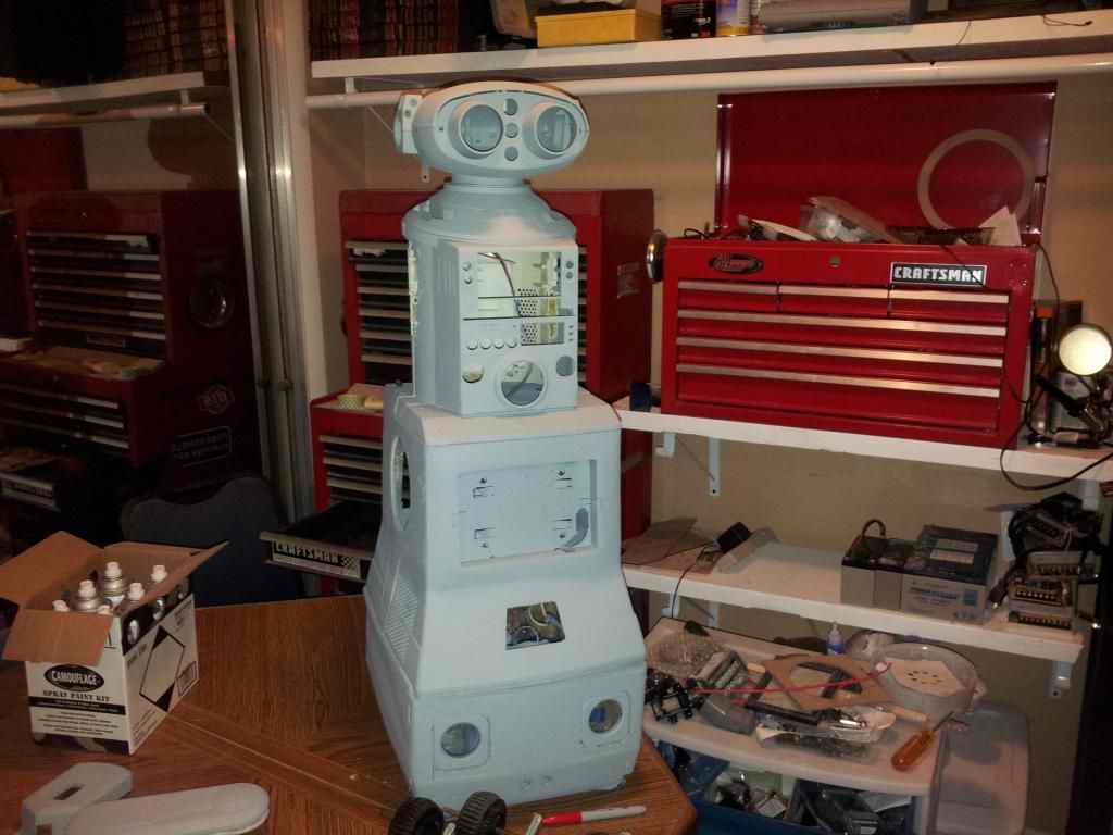
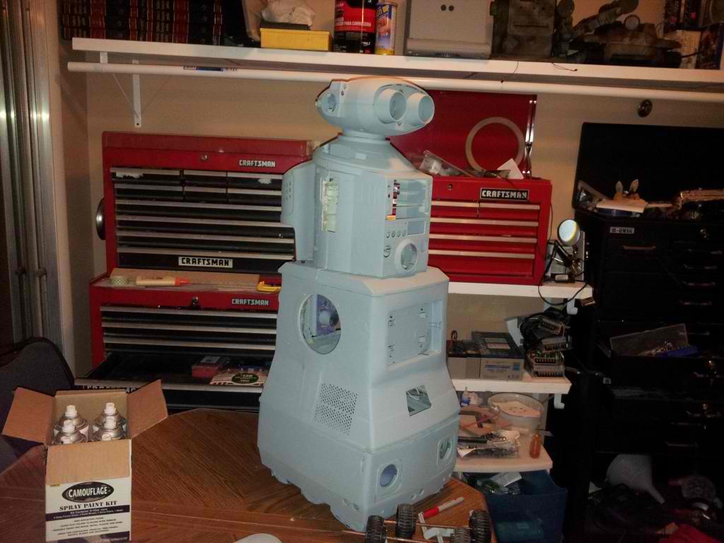
At this time im getting the body ready to start putting things together. The fun begins!
User-inserted image

User-inserted image


ARC Pro

Upgrade to ARC Pro

Take control of your robot's destiny by subscribing to Synthiam ARC Pro, and watch it evolve into a versatile and responsive machine.

#2  

First post (er...reply?) Looking sweet! Im jealous!

#3  

Thanks Troy, I am looking forward to getting him together. It looks like I may start installing equipment soon because.my.painter is busy this week . That's ok. It still would be great to see Jarvis mostly assembled even if he is still grey. I would like to have him rolling around in some capacity before Halloween , freak some kids out lol , drive him in a movie theater lol. I know the people at the local radioshack would be surprised to see him.

#4  

Or the local shopping mall.:)

PS. Dont forget EZ-Robot signs/stickers on the robot. You might not be permitted to hand out flyers though.

#6  

Just dont bring lil bro's Warrior camo omni to any theaters or malls. lol We might not see it for a while as it may be processed as evidence. LMAO

#7  

Oh IM sure it would get some attention from people thinking those guns are real lol

#8  

Feb 1012? You are much older than you look. Also, you have been working on the project a very,very long time. micro processors were not even out until 1975.

ha!ha! -I'm Joking. Jarvis looks Professional. Can't wait until he is assembled. Good work Josh!

:D

Germany
#9  

Josh! I am so anxious to see the arms moving. I still cant image how they will move the way you want them to with the heavy duty servos. Pls upload a video when you have one moving. Mike PS Have you had a chance to mail out the spares?

#10  

Wow... the primer is down. He looks really awesome Josh.

#11  

@mike I sent the spare parts out and got them back today for incorrect postage. I tried sending them in a flat rate box and they sent it back. I will need to go back to the post office.

@Sam thanks! It's great to see it in one color lol. I will be making the elbows and get the arms moving shortly.

#12  

Yeah I bet it is.

Can't wait to see this guy moving around.

Germany
#13  

Hi Josh! Oh no! How could they. Send me a message if I need to wire you something though PP - also, if you dont happen to need the Omnibot arms anymore and they would fit the spares box still, let me know. Man, I am sorry for all the work you have with psting those spares. I am sure you got better things to do - such as posting news on Jarvis here =) Thanks Josh, I really appreciate you helping me out with robot spares!

#14  

No problem mike , I love helping others =) I'll go back to the post office tomorrow and I'll take pics of receipts

#16  

Im sick so i cant work on the robots today , must be food poisening or flu. Great news is the much needed 300mm servo ext cables came in. On jarvis i must actually double up these to get to arm servos and neck.

User-inserted image

#17  

looks like it getting there was watching a movie on my vacation trip called "short circuit" may be 10 time i seen it and near the end i see omnibot 2000 robot with my favorate robot johhny five CANT wait to get back to work on my omnibot 2000 project,going to be a very good design
JOSH keep adding to yours but dont over do it ,or you may have problems

#18  

Man Josh! He looks great! Take it easy - your robot will always be there for you when you are ready.

#19  

dont rush JOSH,get better first and take it easy i had the flu awhile back and took a week off and didnt do much,chicken soup is real good for the flu

#20  

Josh! Hope you are feeling better soon.

Also, I noticed in the picture you had servo extension wires. I was wondering how heavy duty they are and how much they cost and where did you get them. I got some on Ebay that were extremely cheap, flimsy and did not work very well.

Well, when you are feeling better, maybe you can share this information with me. I will Eventually have to find another source for these cables.

I posted this already, but it did not stick for some reason.

thanks,

Mel

:D

#22  

Fans are on the way . F12 arctic 120mm fans are high flow 74 cfm and .3 sone at 1350 rpm.

User-inserted image

#23  

Jarvis needs plenty of cooling given he has a full computer a couple ezb boards , voltage regulators for drive motors and servos , the pc power supply and Sabertooth 10x2 H Bridge.

Best part is these fans are 6 dollars each and have won awards for silent operation while having the high 74 cfm rating. http://www.arctic.ac/en/p/cooling/case-fans/77/arctic-f.html

#25  

servocity has some very heavy duty cables,ones you got JOSH ,dont look good for high current servo's ,they look like a #26 wire what i do is i make my own cables and use the correct gauge of wire for each type of servo need to pick the gauge to match the stall current of the servo,same for h-bridges too

#26  

I'll try these and upgrade if needed. I bought these because of price send plugs are already installed.

#27  

yea you need a special crimper tool,you need different sizes also,i bout a lot of different ones to have on hand ,never know when one is needed,i like building custom cables for many reason IDC ribbons are mostly the hardest and crimpers are high cost

#28  

Ok so I picked up the screws and washers to make the elbow joint site maybe I can get those together after work.

#29  

User-inserted image

The f12 arctic fans have arrived. Two for dusty two for Jarvis. I will test the flow of these fans tonight. The box says they have a 6 year warranty

#30  

User-inserted image

XT60 high current connectors came in so I can solder leads and connectors to the battery packs and other areas of Jarvis.

#31  

I'm not sure how I feel about this. I was thinking of putting Mr clock radio head I have inside the Robbie Sr helmet. I do have the additional challenge of finding a new place for the ez robot camera I took before and after pics of camera looking through the dome and it's not that bad. Take a look guys. This is mostly a looks issue and tell me what you think. Remember I have a neck that turns tilts and nods for this to attach to.

User-inserted image

User-inserted image

User-inserted image

#32  

User-inserted image

Pic looking outside through dome

User-inserted image

Same pic without looking through the dome. You can see some distortion in the first picture.

#33  

What do you guys think. Stick with my omnibot 2000 head I already have ready to go or would it be better looking to have Mr clock radio inside this helmet.

#34  

Hmmm... Take a pic with helm shield up.

#35  

The original head is nice. It's a better size I think.

#38  

Yeah original head

Germany
#41  

Original head for sure! This is what the Omni 2000 is all about!

#42  

Haha the jury has spoken! Original head it is.

#43  

They Both look Great, but the Original Head Looks Best.

Mel

#44  

Thanks everyone! Hopefully I can get the arms together soon

#45  

Jarvis has 2 ezb boards

Anyone want to help me organize where servos and sensors are plugged in? Here is the list of sensors that are a must.

Right arm 4 servos Left arm 4 servos Neck 3 servos

Drive H Bridge sabertooth 12 x 2

Front radar servo

RaDar ultrasonic

Ultrasonic in each hand 2

Mp3 trigger board

Ambient light sensor

Face ultrasonic

2 current sensors

4 contact sensors / switches to detect collision

2 Ir cliff sensors

1 ir distance sensor also on radar turret

Battery voltage sensor

Optional sensors at this time

Close to floor center ultrasonic

Side close to floor ultrasonic x 2

Ir directional sensor

2 directional sound sensors

Ir illuminator trigger on

I think there were other potential sensors but this is the most of them.

#46  

User-inserted image

I know my drawing shows four sides but most likely I will only do front and back bumpers. Well see later but 4 sides means four digital ports My idea is utilize two digital ports. All front bumper switches would be wired in parallel ans same goes for sides and rear bumper. The digital port would read zero or off but if a switch is pressed on any given side the robot knows it made contact with a wall or object (like pets or kids feet etc.) The bumpers would be discrete and have 2 or 3 lever type switches per bumper. This is a safety backup incase radar did not catch the object and avoid it so that no one gets hurt especially the robot. I think this is a simple switch system that will work.

#47  

Ok running at 7 volts I noticed the drive train made much less noise but because I have two motors running each side it still pulls the 45 pounds of weights no problem. I purchased a 10amp step down converter so I have options to tune the voltage the drive motors run at. The unit is smaller than I imagined....

User-inserted image

#49  

Ok tonight I wanted progress! I began making the elbow. It has to be cheap , strong and smooth moving with zero play. Here we go....

User-inserted image

User-inserted image

I drilled out a 1/4" deep hole for the machine screw to sit down into.

User-inserted image

Several drops of superglue gel hold the screw head in place so it can epoxied in a stronger manor.

User-inserted image

User-inserted image

The screws were epoxied into place

User-inserted image

Drilled the holes for the bolts to slide through.

User-inserted image

I superglued washers into place that I drilled out to be the same inner diameter as the screws

User-inserted image

Drilled out washers are also glued on the inside and outside of the wrist as well. The smooth surface of the washers provides a smooth bearing with zero play for a great elbow;)

#51  

Very cool look. Will you be using pushrods to bend it?

#52  

Very nice Josh! I wish I had thought of that for B.O.B. But now he is going to be a battle bot so not important. lol

#54  

Very nice.... I like the way you did the elbow.

#55  

Thanks guys! I will attach servo horns and rods tonight and test its movements

#57  

User-inserted image

Push pull linkage is together;) will post two vids testing

#60  

Wow! That works SOOOOOOO well Josh! I sure wish I had done something like that on my omnibot. Great work!

#61  

Thanks Brett! Soon you will have your Rad 2.0 base maybe next tues or wed:) I did the long video to show everyone how it works. Im going to make a stage setup just for youtube videos so I dont have my stove in videos anymore lol and look more professional.

#62  

The arms are awesome. not loud either... awesome job.

#63  

Yea and I have not lubed them either. So squeks rattles or whatever. Thanks for pointing that out. I didnt notice it was not crazy noisy when I took the video. The servo does make a bit of buzz noise but im wrapping it in dynamat to reduce that too.

#64  

Josh, Just wanted to say what a cool looking robot you got there. You do very nice work. I am following your progress closely.

Rex

#65  

@rgordon thanks I appreciate the comments. Really though positive comments after a long nights work getting somthing working smooth really makes my day.

Im getting restless working on the gun robots for my little brother and sister. Jarvis needs to be worked on lol

I already know jarvis is getting a bright red iron man type paint job. However im trying to think of colors to make dusty....dusty ofcourse will be together before jarvis

#66  

Wow, nice job! Did you take molding lessions?

#67  

Thanks merne . I learned most fabrication from custom car audio and performance installs. Its amazing all the other places you can apply the creative experience. Before jarvis and dusty project I never made a robot before so it is especially challanging because im learning about hardware , the physical mechanics of things and also I must learn code. These projects have been equal to taking a college course almost full time.:)

#68  

merne, Is your avatar a picture of a robot you built? Is it made from an ElvisAlive! ? If so , can you share some pix with us? It looks cool.

:P

#69  

I believe I will drill the holes for the elbow servo to mount down to tonight. Also assemble the shoulder pan brackets and attach those to the upper arm. Maybe tonight we will see Jarvis with arms mounted to the body?:)

#70  

Cool! Hey, you could always do a reverse paint job on Dusty. Gold with red accents.

#71  

I would need to change his name to midus then lol

#72  

Jstarne1, I know what you mean, on the never build robots. I too just started. And man there is a lot to learn.

#73  

MovieMaker,

It's a combonation of ElvisAlive Mask, and A head from Rotbotsquared, I cut the lower jaw off and installed a moving mouth/teeth with servo. Removed the lower eye lids, then added the ElvisAlive mask. Then once I got the EZB, will the rest is history. Now it works without having to know how to program. I call him Ricky. I am going to use Ricky for Halloween.

Funny thing is, 4 months ago off work and bored and before I knew about EZ-Board. I bought the head and then added EZB and now it works! Go DJ! in the mean time while surfing the web, I found Robots and Androids who was selling the Wowwee Robotics' Alive Elvis. So I bought it. So I have Ricky and Elvis. And a used R2D2 on the way. This may be down the road maybe 2 years, but I plan on making Elvis mobile.

BTY this is all new to me and I am learning a lot and still know so little just on this borad alone. So thank you and everybody else for sharing. I will post some Pics tomorrow.

#74  

Its cool you animated it with servo s but your avatar creeps me out Halloween style lol

#75  

Alright I took a couple days off from the Jarvis project and now im ready to build and assemble the shoulders. In my shoulders there is a robotzone gearbox powered by a power hd 1501 mg once I modify the servo. Next is the lynxmotion pan and tilt bracket also with a power hd 1501mg servo. The servo side will be mounted the the shoulder and 4 machine screws will attach each bracket to the servo city modified hub.

#77  

Great question . A couple weeks ago i talked to clint the painter and he was swamped with insurance paint jobs but he should be about done with them. I will send Jarvis to paint once the painter is ready as I dont want the painter to have Jarvis for weeks waiting on the insurance job to be finished. While im waiting on the painter I plan to work out details. Put in bump switches and I still have two small 4 inch areas to bondo and sand then seal with primer. I basically want to physically test the primary function and movement of the robot to ensure there are no fundamental changes to be made that might result in me screwing up a pretty red paint job. So its not a big rush but I would like to hand Jarvis over before the end of the month and maybe dusty too to get them done at the same time..

#78  

Tiny update! My sound solution came in. A sony brand analog stereo condenser microphone. It has seperate right and left position mic elements so Jarvis can hear in stereo. Each element has a screw so I believe I can extend the wires and actually position one element on each side of the head near the "ear" area.

User-inserted image

User-inserted image

#79  

Wow I just realized I have not done anything productive with Jarvis for a week now. I have been distracted getting the mech robots done. It wont be long they will be up and running. I recieved my ezrobot shipment with servos and cameras to install in them. Next im waiting for the motor controllers for them..... which agian was my distraction. So my next steps were to install shoulder brackets and modify two servos to continously rotate for the robotzone servo gearbox.

#80  

It is so easy to get distracted with other robots. So many robots so little time haha.

#81  

I know right? Im going to text my painter tommorow and see when he can paint the robot. Tommorow I plan to get most or all of the shoulders together. I need to still mold a couple areas on the base and get the claws reinstalled so it could be painted.

#82  

Update : just letting everyone know I didn't forget about Jarvis. I took a couple weeks off working on the saltwater tank and ive been on a weird alternate training schedule for work. Sometimes it really helps when you set a project aside for a little while because I had to work on the design for the 12v psu to the computer and video card and it must also be able to plug into the wall and charge or return to a dock. Each of these things by themselves are done on a regular basis by robot hobbyists and commercial robot manufacturers. I believe I have a big picture worked out I will share in diagrams tommorow and I need to get parts to do these mods.

#83  

Cool, I'm excited to see more Jarvis updates.

#84  

hey that cool saltwater tank i have 50 gallons tank i set up for that what size is your tank,also just add a special wall tank on my wall

update on my omnibot project i just got a large order of mcmaster parts and servo city and will be starting on my arms made with metal inside with plastic omnibot arm on the outside look for photos very soon

#85  

The smart aquarium is 55 gallons

#86  

i think thatn same one i got,other ones 40 gallon ,and five 10 gallon tanks plus 8 gallon wall tank you getting any saltwater fish for it

United Kingdom
#87  

@jstarne1 hey josh, I was just wondering if you had any close up pics on how you connected your pan / tilt mechanism to the head / shoulders? The best I could fine was this, but I couldn't see how you'd mounted it.

#88  

@matt honestly they were hot glued down for testing at that time. The brackets have screw holes I plannedn on using 1/4" self tapping screws and predrill the holes for good bite. I will get back on jarvis soon as everything is mounted up in squeegee so I can play with him while Jarvis is away. I am a complete idiot and accidentally threw away my sander so I am buying a new one Thursday and will finish up some things so I can get Jarvis to paint.

United Kingdom
#89  

@josh for the shoulders, did you / will you be fixing some wood into place and attaching the mount to that? Will be really good to see this project finished, I think i pretty much read the whole of the two forum threads:) it's really inspiring stuff (the squeegee project too).

#90  

@matt the sides of the omni torso have a hollow cavity. I filled them with a few ounces of epoxy to makr the sides stronger and then predrilled mounting holes for the servo city 5 to 1 ratio servo gearbox. It seems to be plenty strong to support the 3 pound max lifting capacity of the servos and then some. I prefer epoxy mounts over wood if there is a practical area to form them.

#91  

josh why do you need another set of arms,sorry need both of my omnibot arms for covering for my aluminium frame,and same with the second omnibot i bought

i saw a great deal at petsmart for a very large tank 150 gallons with stand ,getting it christmas looking to put very large saltwater fish in that one

#92  

@robotmaker i was looking for arms to add to dusty. It was just an idea. Since dusty is a service bot i really don't need them.

#93  

Hey Josh, if you want them you can have the arms off Bob for Dusty - one is that gripper claw. I won't need them with the guns. I can ship them with your Robie Sr. head (I am not going to use it) It's up to you, just let me know.

#94  

just got a very big robot emiglio ,its bigger then omnibot and B9 robot,plenty of room inside to hack for ez board also got the best laser range finder you can get hokuyo URG-04LX for $1000 great deal it goes for $1200 ,hope soon that DJ will have a interface for it,may use it on my omnibot project

#95  

@bret sure send the arms with the robie sr head. I will probably use them;)

#96  

JOSH i guess you be glad when you get your omnibot project done and codes made have you got it painted yet,or you adding more updates i added photos of my arm design on my omnibot project page

#97  

any progress yet on your omnibot project,getting some tools in this tuesday mostly my table belt sander to finish of my aluminium frame,hand sanding and using a file take much much time also my mill machine came in last friday ,still have about 16 big tools to come in

#98  

User-inserted image

User-inserted image

User-inserted image

Heres an example of how im doing cooling on Jarvis and dusty. A large hole with 120mm fan and ouside covered by a matching speaker grill. This case is going to house Jarvis computer till im confident he can dock , self charge, and reliably avoid stairs and drop offs like the front door.

#99  

are you going to use a IRONMAN mask for his head,they have one on ebay ironman helmet ,just like the one i got for one of my omnibot projects ,transfomer helmet getting it tuesday

also i found out i dont really need any cooling on my design,using super low wattage items ,like sensors and more fist it does many thing ,no cooling is needed ,save you weight and current(battery life) and second the same using using low current ,sensors,motors and boards it says on current used (battery life)

#100  

No I planned on using the original omnibot 2000 head. I want Jarvis to be recognized as a highly modified omnibot 2000. I changed shifts two weeks ago and ive been making early nights. I accidentally threw away my power sander:( sad right? Lol. I have a couple areas that need body work before paint. The area on the front edges of the base and the rear of the base where I extended it out 1.5 inches.

#101  

Hey Josh, I have an extra sander I will throw in your goody box.

#102  

i like a good table belt sander,easy to use and not heavy in your hand and does a much better job most are $179 like the one i got and has a side disc sander,i have 3 other sanders i got for other jobs,like a detail sander for getting to close places ,palm sander for light sanding and handheld belt sander for very heavy sanding,but table belt sander is always the best nice sanded shaping and sander doesnt move or heavy holding it my omnibot project using the omnibot head,nextone might use the transfomers helmet for it or the smaller omnibot 5402 i have also bought 4 of them i guess you say i have a omnibot family of 7 total

#103  

Sweet! I get a sander from bret. Today is my Birthday ! Woop woop!

#104  

wish i had a extra sander,i would give it to you too

#105  

happy birthday Josh!

#107  

is this project DEAD ,havent heard of any update in long while

#108  

As you know he is working quite a bit on his other project. He likes all his projects and Jarvis will get some love when the time comes.

#109  

yes i know,just joking ,JOSH IS a lot like me,i start on one project and then start on another girlfriend of mine not happy with not working on the robot she bought for me,but still like my omnibot and helps me work on it,going to give her a very big gift ,long long vacation to jamaica with me about june 1 for 3 weeks

#110  

Happy Birthday, Josh!

It is hard to have a birthday in Dec.  People always say "here is your birthday-Christmas present."

I have a son that was born Dec 24th. We carried him home on DEC 25th in a Christmas stocking. It was quite nice.

:D

#111  

Hey Josh, has Jarvis been painted yet? I would really love to see some pics.

#113  

JOSH hows it comming any changes yet

#114  

Nope no changes yet. I bought the upper half of a omni 2000 so I could rob his arms and torso for dusty. I might do a dual camera setup , one in each eye since the "camera nose" has become very popular. It was simply to cold and wet to be productive today. I am starting to plan Squeegees brother which is another robie jr:) I will post sketches.

#115  

Thats my plan for my full size johnny five robot I did buy a stereo camera using 2 camera,s and a special board

Germany
#116  

Hi Josh! Do you happen to have an Omnibot 2000 head as a leftover? Any more gears you wont need anymore? Mike

#117  

I just your email mike;) I bought a partial omnibot 2000. The upper half torso w the arms , torso, arms, head.... ect. I bought it mostly for misc parts. So do you need a head ?

#118  

i think the head on mine is good,and i might have one left over

#119  

You know I always take care of you mike;)

Germany
#120  

yeah, I know, haha! =) Yeah, I need a head and the lower plastic of the bot - the part where the wheels and the gear box sit in. So I pretty much need the top and the bottom of the bot, the inbetween I have.

#121  

Very inspirational Josh,and I love the (good)peer pressure and the encouragement!:) Take a rest and get healthy.

#122  

JOSH your christmas gift shoud be comming soon

#123  

@MikeDC LOL you already have LOTS of Omni2000s!:)

Germany
#124  

@ Troy! Haha - yeah, I have a few but still need a few parts to complete another one. =) You never got back with me about your spares.... Mike

#125  

Getting my 3rd in a few days,its all apart making it super easy to make another EZB OMNIBOT 2000 project,so far the other 2 in good shape,on one no changes at all. Straight OMNIBOT 2000 RESTORE.

Look for this weekend for some photos i am putting up on my omnibot 2000 project

#126  

JOSH did you forget about this project,been very long since i see anything

#127  

Nope I have not forgotten Jarvis , Im just going to get Squeegee moving first just in case I get ideas for Jarvis while im working on a different robot.

#128  

LOOKING to see the paint job and EZB codes to see if i needed them,coding looks very easy but when you have another person post thier codes it makes a lot faster.

#129  

ALSO my girlfriends wants me to build server type of robots and plays or controls music and TV and to chat with while i am gone

#130  

I assure you Jarvis' s code will not be easy , there are lots of sensors and tasks planned for him.

#131  

all mine are the same,like my omnibot project is going to use a lot of them I use alot of sensors mostly for navigation,and making a special board for then to use only ADC port instead of 2 or 3 EZB'S ,its called multiplexing can have over 100 analog or digital or servos plus it much much faster ,no cpu is used like all scripts are done on one EZB

#132  

well planned and efficient robotmaker! What is the type/name of the multiplexor chip your using, please.

#133  

Wait did you say your making it to where there is no pc needed to run scripts? Is it really as ezb anymore then?

#134  

JOSH no it uses EZB ,IT USE ONE ADC port and a few digital lines

IROBOT one for analog is called CD4053,then there others for digital

#135  

@Josh I believe robotmaker said he would not need more then 1 EZB and use a multiplexor to create multiple inputs:) "instead of 2 or 3 EZB'S ,its called multiplexing can have over 100 analog or digital or servos' " if I may speak for him:)

#136  

YES and multiplexing is very easy,also i use CD4051 not CD4053 as i posted but they are both multiplexer chips ,can easy set one up as sensors ,and one as battery monitor and more

#138  

IROBOT thats about the same circuit thats needed,only IN is the output and 8 inputs chip can be demultiplex or multiplexer since its bidirectional and CD4053 is same only dual 4 channel ,same data sheet for both

#139  

OK Josh you did it, sending me videos to lure me in.

But you know me and now I have questions. Where'd you get the replacement motors? Your gear box is different than mine, think the motors are the same size. You mentioned in the video that you added some other gears, how and where?

Now as far as covers. Figure out how tall wide etc you want them. Or even just one cover. I will send you the solvent, plastic and instructions on how to make it in minutes. Once you do it once you're gonna be hooked.

#140  

yay Sam your back! I'm at work not on break I'll respond to the rest later.

#141  

Oh there's no rush. :o)

#142  

SAM havent heard from you while and your robot designs ,hows the cute little MINON doing

JOSH we going to see some changes soon on your omnibot design

#143  

Yay Sam! It is good to see you post again! You have been missed. And Josh, we are missing pics of Jarvis. What's the haps?

#144  

Thank you, I have been around just focusing on other things. A bit discouraged about my dude but Josh here has managed to lure me back in. :o)

#146  

The minion had way to many limitations so I dismantled him. Started the franken bot dude and got discouraged with the Robosapien body and base. Ya know the one you sent me the Hearoid body.

#147  

SORRY to hear that,dont give up,i found a another head for hearoid robot if you need it,can let you have it for free only pay shipping,but will have to wait 3 weeks in china for work

#148  

I have a head, thank you.

#149  

@Sam hey I been moving all week , the motors I got from robot maker but can buy them from robotshop too. The motors are RS585 Mabuchi I believe. They are the motors a roomba uses for the main brush. Thank you! I will pull the gearbox out and get some measurements.;) the room a motors are just about the same size but they have a noticeable increase in torque over originals. If you are looking for more power and don't wanna buy those then maybe you could use two more original motors.

#150  

SAM i can help you out and give them to you free,just little ,i have a lot of them Since i still need your help on fixing my tail on my MYLO puppy.

#151  

I said I'd help regardless all you have to do is send it to me. I'm not sure I want to do anything with the current gear box. I think I might use that for something else. I'm planning on going to Pick and Pull and getting window motors. Will see how that works out.

#152  

OK so I picked up a new SKILL brand Octo hand sander and three sets of sand paper. 60 120 and 220 grits. I went to start setting up the table outside and turn about my ext cord was too short because I don't have a outside outlet. After I finally got back with the new 25 ft ext cord it was getting dark because its 823 pm. I can still do the initial filling with bon do on certain spots now however. I will mark them with a black sharpie.

#153  

Dang it , I get home and we lost the creme hardener for the bondo.

#157  

User-inserted image

User-inserted image

User-inserted image

User-inserted image

One of the things that does not stand out it I filled in all the ridges that wrapped across the front of the chest. No one that has seen this pic yet noticed I shaved it smooth. Also there was a tiny overhang along the bottom of the ridges/ speaker area and I completely filled and molded this together. I filled the previous led holes because it looked crowded and I already have 6 led mounts on the head of Jarvis and 4 on the chest. This was intended to be for night time IR vision so they won't be visible. Only two on each side of the head and 4 along the base will be visible light.

User-inserted image

User-inserted image

User-inserted image

#158  

I had to finish molding in the rear of the base where I had to extend it out nearly 2 inches to give plenty of room for the modified quad motor gearbox. I believe this is all the mods I needed for the gearbox. The only other mods on the bottom I need right now is two casters on the bottom of the vacuum head because the original rollers were never meant to slide side to side when the robot will turn left or right.

#159  

I'm letting primer dry overnight because it rained and humidity will make the primer gum up my sander. The molding of the rear extension is almost done. Just a little touch up and its good to go. The two challenges I have at the moment are cutting the front chest piece for the DVD drive and finishing molding in the ARC reactor. I been putting this project to the side through the holidays and moving. I really want to see Jarvis in one piece and start fitting electronics soon !:)

#160  

User-inserted image

User-inserted image

User-inserted image

User-inserted image

Here's pics of the mid section and the vacuum backpack. Today Alequa wanted to sand on the backpack. He's still new to custom molding things together but he is learning.

#161  

Here is a pic of Jarvis body stacked up before I started back working on him

User-inserted image

#162  

OK lead acid batteries are reliable and cheap , however I want to really lighten up the load. I currently have room for two 12v 9ah batteries but in the same space as one lead acid I could have two lipo. I believe I will only have two lipo though. Here's the specs from hobby king.

User-inserted image

Spec. Minimum Capacity: 5000mAh Configuration: 3S1P / 11.1v / 3Cell Constant Discharge: 20C Peak Discharge (10sec): 30C Pack Weight: 412g Pack Size: 145 x 49 x 26mm Charge Plug: JST-XH

4.18 v per cell is 3s = 12.54 volts charged 11.1 volts is considered discharged and time for a charge.

They are 23 dollars each today so maybe I will buy two.

#163  

5000mah 3S lipo pack is 412 grams = 14.53 ounces . That's less than a pound! Also I will note turnigy has nanotech versions of their batteries which are even lighter.

The power sonic 12v 9ah battery is 6 pounds. Its true I would need two of the lipo packs to exceed the battery run time but that's still 1 pound 13 ounces instead of 6 pounds!

#164  

Thank you Josh for "thinking out loud":) One of your many talents is to see a "mundane object" and invision something else as in JARVIS! Something like turning a chunk of marble into "David"....IMHO your the best "robot body hacker" on this Forum! :)

#165  

Hey thanks man! Hearing a complement like that makes me feel like a million dollars. Its all about dreaming something up into something better;)

Oh what do you mean by thinking out loud? Just wondering;)

United Kingdom
#166  

@josh, I would thoroughly recommend LiPo batteries. Like you said, you can fit 2 in the space of 1 SLA and for weight, they weigh barely anything (which is why Melvin rocks on his base, no weight at the back).

I've never looked back since replacing the SLA for a LiPo, just make sure you have some kind of monitoring in place, either the EZ-B or a cheapo balance port monitor.

Jarvis is coming along nicely!

#167  

I believe a power cutoff controlled by ezb may be a good option. Well work that out when we get there;)

#168  

Josh,

I know different application but we got one of those batts for the hexacopter and it was ok, ran down pretty fast. These are a little more expensive but so much better. We got the Venom 14.8 5000 mah 25c. It doubled the time from 10 mins to 20 mins.

Thinking out loud is something I love too. The expressing of your whole thought process. Most people don't do that.

#170  

Thanks Sam , I like to share ideas as I have them , someone else might need it nor have a better one to share. Speaking of Sam had a rocking problem and I sent her some casters to put on the corners. Perhaps you could do something similar.

User-inserted image

Just put a layer of foam in to keep some tension against the floor m

#171  

Josh I ripped off my whole base and am redesigning it. Blah!

#172  

You should do tracks , or like 8 skate wheels:)

#173  

I am actually thinking of using the 4" lawn mower wheel.

#174  

Wow , rubber wheels like that will have lots of grip.

#175  

Can you link me the battery your talking about?

#177  

Here's the casters I have for Jarvis for the vacuum head to ride on. I chose plastic to prevent floors from getting scratched but a metal version is available I could swap to if I need. 3/8" ball

User-inserted image

User-inserted image

#178  

Wow they are sure proud of that battery! I could buy three turnigy for that price. I will try them if turnigy does not meet my needs since I have used a handful of their stuff.

#179  

Does it feel good to be working on him again?

#180  

Oh yeah , I feel like I should have been working on him the whole time lol. Its crazy to have stopped so close to getting him to the paint guy.

#181  

I was wondering about that but I get it. Sometimes you just need to step away and take a break. I know I did but I was more frustrated.

Maybe Jarvis will be making an "in progress" appearance at Maker Faire?

#182  

By maker fair Jarvis should be painted and have head and arm movements and facial / movement tracking, he should be presentable by then.

#183  

Wow.... that would be awesome. If you are hoping to impress them, bringing Jarvis will do it.

#184  

OK slight updated pics and I will add some text. You can see the improvement in comparison to the first pics on the thread.

User-inserted image

#185  

User-inserted image

This pic shows direct view from the rear. The bottom of the mid section will house the PC upside down. The normal connections will show through here. I'm still thinking of having the graphics card and I bought an ext cable PCI express x16 which I tested and seems to work well. This is so I can lay the card on its side instead of vertical. The two monitor connections and video card air intake are right there. I will do a bit of test fitting to make sure this is doable. I extended the height of the base specifically so I would have extra room for this video card;).

#186  

User-inserted image

The first pic you can really see my problem. The rear is about a half inch off from fitting correctly in the first picture. I believe I will need to take a flat piece of wood and hot glue it in place and then fill the gap. It needs to be thick so I can epoxy L brackets in to hold nuts. Those nuts are how I will mount the back plate of the battery compartment. Even with two fans and a center vacuum inlet tube I should have a fairly spacious area here for 2 to 4 lipo batteries.

User-inserted image

User-inserted image

User-inserted image

#187  

Separate power for the Nvidia GT 550ti - The video cards power would be on a switch by the way , this way I can power it off and default to onboard video when autonomous. I'm sure autonomous use without me being home won't happen till later this year but there is no reason to keep rewiring stuff. I will have a separate power supply fed from the battery/ outside power desperate from the tax power supply. This is because trying even the biggest 240 watt M4 atx power supply from mp3car.com still could not keep the PC on beyond boot if the video card was active. If anyone has ideas for separate power let me know and I will post mine.

Power draw for the current Motherboard - anyone know of a program I can downloads that estimates power usage? Basically I can guess based on specs of all the hardware but something real would be nice.

United Kingdom
#188  

Anything that estimates power usage is generally very inaccurate in my experience.

With laptops I use battery eater (used in the infamous Windows XP vs Windows 7 battery life topic/tests) but it reads and logs from the ACPI, if the battery isn't connected like a laptop's battery I presume the ACPI wont know about it and will assume it's running on mains AC.

There is always this calculator which will give you a worst case result.

#189  

OK so without the hard drive and DVD drive it gave me this with just the memory , CPU and motherboard

User-inserted image

Then once I selected the high speed SATA drive , Mouse , keyboard, 4 USB devices , 4 fans and a DVD rw drive it estimated this...

User-inserted image

#190  

With the video card Nvidia GT 550ti it went up to this...

User-inserted image

#191  

It looks like once ARC is loaded and the video card power is off that the motherboard should be drawing about 35 watts. With 120 watt hours of battery life ( two 5000 mah packs) that's 3.5 hours run time for the PC in the worse case. Not too bad:)

United Kingdom
#193  

Sounds about right. It may pay to run from USB memory stick or SD card, however speed is reduced but power usage is reduced by a lot. There's a lot you could do. Also, I am pretty sure you can turn off the gfx card via windows rather than hard wiring it

#194  

I don't think I will go that far for energy conservation. Lol I like my speed. Its very fast considering it has a AMD dual core 2ghz 270u but my board can over clock it as needed to 2500 MHz. Its TDP is only 25 watts. Its a tiny bit more than a atom CPU as far a power but great performance. 7.8 on the win 7 experience rating.

Hopefully it won't rain today so I can get back to working on the body. I need to put a to do list together.

#195  

Have you tried Wunderlist? It's a great app for checklist style things. Have you thought about adding more batteries to keep everything on?

#196  

Yes more batteries are an option but to start out two will do fine till he is autonomous

#197  

Oh I thought that I read you were having problems with hims shutting down when stuff was on.

#198  

It was because the video card draws more current than the atx PSU could support. Oh good news then tent was still there lol

#199  

Woo hoo... good thing it was there.

Awe I see. Can you give a video card separate power? Or do you have to up the PSU?

#200  

Yes that looks like the only option is give the card its own 12v regulated from the battery.

#202  

User-inserted image

User-inserted image

User-inserted image

Here is where I need to cut for the DVD drive but its storming outside.

#203  

OK back to work on Jarvis for some little clean up spots because he is going to the painter today!

User-inserted image

I fitted the DVD drive in the front with the dremel. It took about 20 minutes.

The only places I'm not worried about finishing are the back side and back vent holes. Its not a big deal and I realized I'm trying to put way too much detail in my very first robot. ( even though I've had other projects after Jarvis he's still the first child lol)

#204  

Jarvis is looking good. like the dvd player idea.

Where are you getting all this stuff!

this is a very unique omnibot.

#205  

User-inserted image

I'm using 6 inch Memphis audio grills to cover vent/ fan holes in the sides of Jarvis's body. Its a great car audio brand but I'm never going to surface mount a speaker and cover it with a grill.;) even on my robot there's no tacky grill over my speakers lol.

User-inserted image

@Techno pro - thank you , one of my goals with building this robot is despite all the physical modifications my goal is to utilize every single piece of the original Omnibot 2000 shell. Even original wheels.:) I want the most advanced Omnibot 2000 ever!

#206  

The pink material is bondo body filler as I don't want everyone to know they are just speaker grills;). Sorry Memphis Audio , you don't put in on the project you don't get your name on it:(

#207  

User-inserted image

Here is the inventory of small parts to be painted minus the grills, vacuum canister, and accessory door in the back of the robot.

User-inserted image

User-inserted image

User-inserted image

User-inserted image

This the assembly of the new arm internals I made. A strong elbow that I cannot bend or flex grabbing it by my hand....wow I love epoxy:)

#208  

Does that mean you are getting ready to go to paint?

#209  

I'm on my way to the painter as we speak....or blog..

#210  

Woo hoo... Jarvis will be all shiny and awesome for maker faire!

#212  

That elbow really does look strong!

#213  

OK parts drop has been made and painter says 1 to 2 weeks and he will do it in between full car jobs. To try to keep him on schedule I told him I'm taking it to a show in 3 weeks so I need it done by then lol. He's a good guy but painters procrastinate.

@troy thanks! I wanted something metal because I thought plastic would be too weak for jarvis to hold 3 pounds.

#214  

Definitely! I sure would have flexed a great deal if it didn't immediately break. Looking forward to the unveiling!

#215  

User-inserted image

Hey remember these Nissan Silvia emblems I had.... They will soon be "Starnes" emblems:) these should go on the shoulders. Though chrome looks good I'm considering the options of painting them too. Any suggestions?

#217  

Oh yes , trace plexiglass and light it from the inside with leds. That's a idea.

#218  

The arch reactor was removed and frame will be painted.

User-inserted image

User-inserted image

I have a spare in case I don't like the painted look.... But I believe I will;)

User-inserted image

The painter suggested I tint the canister like you would tint tail lights. That's usually black thinned out with clear mixed together as well. I plan on lighting the canister from the back so I will consider this. Other wise it will just be left clear. And the purple top painted.

User-inserted image

#219  

Thanks for the updates Josh! Dang I wish I could go to Makerfaire too!...any chance of a "live stream" I believe the color is cherry red?

#220  

You could paint just the red part to match and leave the chrome.

#221  

Thanks Sam , well see hmm

OK new thing i gotta consider is the sensors in the hands/ claws. I drilled out holes for the ultrasonic sensors but the spacing is about 1/2" wider meaning I will need to have wire leads coming from a transducer to the board. Here's the pics.

User-inserted image

User-inserted image

User-inserted image

#222  

Basically I'm thinking since I gotta hot.glue in sensors anyways maybe I could slightly tilt them to shorten the min distance? Or does everyone think just leaving them straight is best? I may make a separate post about this...

User-inserted image

Straight alignment...

User-inserted image

Here's the idea of tilting the sensor a bit , but I don't know if this would be necessary.

#223  

Hmmm.... would tilting it damage the sensor? Well I was more thinking the board.

#224  

The sensor itself would be in the hole and wire leads running to the control board.

User-inserted image

#225  

Oh I was thinking you were using the ping on the board. I damaged a ping sensor by bending the board is why I asked.

I think tilting them would allow you to get in closer with a smaller object. But then straight you'll also get a broader range. I don't know which is better. Maybe you could do one of each and experiment with that.

#226  

For the claw it just needs to accurately detect that 1 to 3 inch area and more than that is not needed.

#227  

I still think you'd be fine either way.

#228  

Less than a inch would be nice.... Like 1/2" but I guess I may end up experimenting and using lots of hot glue lol

#229  

You could maybe tape it in to start.

Have you thought about IR Object Detection?

#230  

Yea but after looking up how the IR sensors work they rely heavily on the angle the light is received to determine a read out. Also the case apparently plays a role and removing the LEDs and sensor from the case further changed how it would read distance. Also it wouldn't work in a bright area or outdoors. So that's why i was going for ultrasonic.

#231  

Poopie. I have some but haven't really used them yet so was unfamiliar.

#232  

Hey Josh, what about the sharp sensor? It is a lot smaller

This is a very common sensor used in robotics and is also called the Sharp Analog Infra-Red Range Finding System. It uses Infrared to determine the distance of an object in front of it. The Sharp IR Distance Sensors come in many different flavors. I use the GP2D12. I prefer to use the Analog version because they are quicker and integrate well with the EZ-B. The GP2D12 can be plugged into any of the 8 ADC ports.

Higher number means closer objects. Lower number means further objects.

The GP2D12 can detect an object within approx 100 cm (3 feet). IR Distance Sensors are not very accurate and are subject to interference. They do not work well in the sunlight also

#233  

Well I already drilled out his claws for ultrasonic sensors so I will try that first , IR will be the backup its just hard to undo those holes lol

#234  

OK Jarvis is still with the paint guy. I suspect I will have the parts back by next weekend. I wanted to start testing some equipment out. I came across a very happy surprise. The external DVD drive I purchased turns out to have a lot more features than I thought. Up to 120gb capacity on a blue ray RW disc , obviously it plays blue ray too.

User-inserted image

In the picture you can see a blue ray logo but I couldn't see these previously without the power LEDs being lit from the inside. Soooo I am watching blue ray to make sure it works.

User-inserted image

#235  

I also love blue ray ,i think i have the worlds biggest collection over 400 movies and getting bigger each day

#236  

Well it worked perfect , I was very happy with the speed both reading and writing was impressive.

#237  

Oh yes my friends... To compliment the release of Ironman 3... Dum DUM DUUUUm! The new Jarvis 2000 Avatar Robot! Is getting his first layers of red.

User-inserted image

User-inserted image

#239  

Last coat of liquid red base.. Before clear

User-inserted image

Germany
#242  

Wow Josh this is really cool! Watched the movie las night and I have to say no wonder why you chose this amazing red! Keep up the good work!

#243  

Thanks guys! I saw this red on a Toyota truck and its really pops! It looks like candy, I am tempted to lick it. Lol. Well this was only the arms and half of one claw. Still have the 3 torso pieces and the base to be painted and I'm hoping I can convince him to do that today or tommorow because I want all the pieces red by the weekend.

Bret- ever find that old laptop after you moved? Thanks!

#245  

It's so exciting seeing him getting painted.

#247  

User-inserted image

Clint was spraying these pieces while I was watching the ironman 3 movie. I realized with some shades and a fancy goatee DJ would resemble Tony stark. The pieces pictured were shoulder handles , two claws , the palm of the second claw, the top to the dust canister , rear accessory door and PC plug cover for the rear.

#248  

I really should get my own paint gun and compressor so I don't hound Clint anymore for these small jobs. If he is not doing a while side of a car or more hes griping he's not busy enough.

#250  

Beautiful!..its coming together! Do all three fingers move or just the "thumb"?

#251  

@ I robot all three move;)

Just got the torso back , could have painted it better with a rattle can but at least its painted. In the future I will do the job myself so there are not all these runs and stuff.

User-inserted image

User-inserted image

User-inserted image

User-inserted image

#252  

User-inserted image

Can't forget the backside.... I will make covers for the battery bay and paint to match but that's a last touch really because I'm not sure how I will wire it yet physically.

United Kingdom
#254  

Wet & dry the runs with very fine paper, then polish it with T-Cut or similar, they should come out unless they are very bad runs.

#255  

Looks awesome.... Is it all painted now?

#256  

User-inserted image

User-inserted image

Dry fit , things are tighter once they are painted. Takes muscle to get things together.. You can see the rad 1.0 robot....they aren't small at around 20 inches tall..

#257  

Outdoors the color is pretty but indoors it catches every ounce of light, the overall "busy" complexity of the body draws your eyes away from imperfections...... I just keep telling myself " its OK josh its your first real robot".

#258  

Stop being critical. It's awesome

United Kingdom
#259  

Guaranteed nobody will notice the minor imperfections, you will because you know they are there but nobody else will look that closely.

Loving the colour indoors, are you adding any gold bits or just sticking with the red?

#260  

I believe I will add gold accents but I don't know where I'm going to accent the gold yet... I want it to be made minimal and tasteful. I'm considering just doing liquid gold accents in grooves of the body that's already there. I'm not going to do a gold face... I think it would be too much gold.

#261  

@Sam thanks , and you helped frame the base for me to fiberglass:)

@Rich your right, I will know its not perfect , but it doesn't matter because half the body is hand made.

#262  

I think it is fantastic Josh, and you did an outstanding job on a really ambitious project.

#263  

Thanks Brett! I really appreciate it! Sometimes I wonder if I'm "up to the eZ robot standard"

#264  

OK here is a few pics of the sensors , I may not use 4 to 6 of them but we will see.

User-inserted image

#266  

I agree with Bret! You are definately the front runner in this class/size robot. Will you have slideshow of progression pics at the booth. People will definately be impressed! Wouldn't it be cool if you could know how many purchases were made due to your showing and demos.:D

#267  

Here's the list of what's in the pictures

-3- ultrasonic surrounding area prox sensors -2- light Dependant resistors on breakout adapter board -2- IR Motion detectors -1- Custom chest LCD assembly w built in sensors ; voltage , current, batt temp and total wattage usage -4-Short range Sharp IR distance sensors for backup obstical and cliff avoidance if ultrasonics don't "see" a object. -1- Long range Sharp IR sensor and ultrasonic on radar pan/ tilt

  • 3-directional microphone on breakout for measuring db to determine direction of loud noise. -2- ultrasonic sensors for object detection in claws -1-wireless EZ Cam -1- ultrasonic in the face -1- ultrasonic pointed up to see when under a table... -1- Sony stereo microphone to hear commands once onboard PC is avail, also has a signal scrubber and 4 watt amp will give the computer a clear loud signal to interpret for voice recognition... -2- spark fun IR 180 degrees sensor... For auto docking to charger ( one front one rear.. Robot turns and follows or beacon to charge) -2- 12 amp current sensors , these will be affixed to a circuit on one digital port to detect if and when the drive.motors stall...

    User-inserted image

User-inserted image

#268  

@Troy absolutely having a slideshow or something is a great idea. Thanks! I'm not sure what class or type Jarvis is lol unless we are just talking about projects based on a Omnibot torso.

Here are closer pics of some sensors. Some of these are so small its crazy. Things have shrunk down over the past 10 to 15 years.

User-inserted image

Don't stereo mic

User-inserted image

Sharp 4-10cm distance sensor

User-inserted image

Directional db sensor

User-inserted image

Ambient light sensor on breakout board

User-inserted image

IR directional sensor from spark fun

User-inserted image

EZ Cam and IR motion sensor that goes in the top of the head.

User-inserted image

or motion sensor and voltage / wattage/ temp/ current display

#269  

I couldn't wait to start working on this project. Its been itching at me and this time its not the fiberglass! I installed the low level sonars for side view and direct forward proximity. Also I installed the motion detector and sonar in the top of the head. Here's pics..

User-inserted image

User-inserted image

User-inserted image

User-inserted image

User-inserted image

User-inserted image

User-inserted image

Last but not least I'm working on a visual audio indicator , like a vu meter that lights when speaking or playing music. Its 4 blue led bar segments and I have a led vu meter kit more to come on that... But its a perfect fit for the area its going in.

User-inserted image

User-inserted image

OK its 1152 pm here and I'm delirious so that's all for tonight. I took the day off tommorow so maybe I will make some more progress...

@ Troy yea it would be awesome to know what kind of business my projects bring EZ Robot;) I will know I have "made it" to the cool kids club when I get Riches approval;) he's probably our toughest one to impress because he has so much general knowledge about the subject. Well goodnight guys!

Oh almost forgot.... Here is the VU meter I'm hacking up to light the blue led bar graph... Lucky me I found one premade to save me a hour of soldering;)

User-inserted image

#270  

Ugh tiny update , Jarvis mini PC that was destined to be mounted in his belly is giving me the blue screen of death and something is screwed up in the CMOS. It forgets the time and date.. Bought a new CMOS battery and it still seems to throw th CMOS error even at boot too. Wow the challenges that come my way... ::scratch my head:: I don't have extra funds to just go to replace Mainboard and CPU so I may not initially have a PC inside Jarvis, maybe remote control for a little while.

United Kingdom
#271  

Have you checked that the jumpers on the mobo are all in the right places? If the clear cmos jumper is missing or incorrectly positioned it could be what's causing those errors. It may even be something as small as a bios update that's needed. Depending on the age of the board it may pay to get in touch with the manufacturer, they could be able to aid you in getting it running or replace it under warranty, it's always worth a shot.

#272  

Poopie about your motherboard. I would call the manufacturer too. Josh I am so excited to see this guy getting put together.

#273  

I never registered it but I think it had a three year warranty. I guess that's a backup option. when I'm back at the house I will check the jumpers. I forgot this board has a clear CMOS jumper... That shouldnt be related to the bsod but you can only fix one issue at a time;)

#274  

Yes! 3 yr warranty. I knew there's a reason I went with Asus

User-inserted image

#275  

First off , Jarvis has to have a power source.... Tada!

User-inserted image

User-inserted image

User-inserted image

Right now it turns on with a touch but I'm going to hard wire it to the ezb once I get to the wiring phase.

#276  

Well I was more thinking for support but having a warranty is great..... That looks so awesome....

United Kingdom
#277  

Glad to see you've gone for the vibranium ARC reactor since I prefer the palladium ARC reactor which is what I'll be putting on my Jarvis (when I eventually get around to making him a physical robot).

Also good news about the warranty but it may be worth a phone call/email to Asus first to save any messing around.

#278  

Yes I couldn't find a palladium premade reactor that was small enough for Jarvis. Everything I found was twice the width and was not practical. This was one of the toys that came out with the premier of iron man 2 the movie.

#279  

OK so I need to do something custom to detect objects in the claw area and right past the claw. First I hack up a HC SR04 for the TX and Rx.

User-inserted image

User-inserted image

User-inserted image

User-inserted image

User-inserted image

I also installed the speakers in the base too.

User-inserted image

User-inserted image

5 watt amp powers the speakers.

#280  

OK transmitter and received pairs have been mounted in the claw housing. They should be able to detect a object inside and directly in front of an open claw....

User-inserted image

#281  

OK time to install the temp monitor and fan controller. This consists of knobs that glow blue and a reverse backlit white/blue display

User-inserted image

User-inserted image

Next I need to epoxy in a shelf right above this LCD that the Blue ray drive straps down to. Directly above the blue ray drive will be the 40 segment led bar I put together the other day. This time for small stuff I'm using hot glue.... Its simply easier. Took me a year I finally broke down lol. The 1/2" holes on either side of the LCD are for stainless steel led holders.

#282  

What I want to know is how heavy this thing will be!;)

#283  

@techno pro this project went through a few months of planning before I started actually building what you see here. Once I had every part I planned on using in Jarvis I weighed everything. Then once the new body was fabricated I weighed everything and rounded up in all cases. Assuming he has 4 power sonic lead acid batteries 12v 9ah then the robot would weight just shy of 60 pounds. Though I will use two lead acid batteries for a while I will upgrade to 4 lipo batteries once I work out a safe charging system I can trust to charge batteries while still in the robot. Using lipo batteries should make the project around 12 pounds lighter.

#284  

Alright both claws are back together now . all they need is the rubber grip. I'm considering casting the originals and molding new ones from liquid rubber or silicon.

User-inserted image

#285  

I'm super jealous of how well polished this project is.:) You may find that you need the extra weight in the base. You will know for certain after you drive it around fully assembled.

#286  

@Troy , Thank you! I'm trying! .... Yes I have had that same thoughts. I am considering making a battery tray to sit right on top of the gearbox and have 2 lead acid batteries there. Try to keep a low center of gravity. I have played with the base some and it feels like it rolls very smooth and turns smooth. That makes it a indoor robot for sure. Just remember it took a year of preperations and a planned buying spree to make it look this polished:). The suggestions and help from others has made this a fantastic collaborative project.

#288  

@Techno pro - thanks! Me too.. I daydreamed a bit today of a to do list. Thank you for your support its greatly appreciated.

#289  

I just noticed you are inspiring many, many people with this project. Including Rich!;)

#290  

Its great! I love it, I like seeing others get inspired and do their own projects too. Some days I like to just help others with their projects.

#291  

I got a new secret weapon in today from those little rascals in China. Its a game controller, media remote,mouse touchpad, keyboard and more. I believe it was 30 bucks.

User-inserted image

User-inserted image

Wireless adapter I bought just for the antenna for the onboard WiFi adapter. I bought two more for the dell towers for a wireless connection.

United Kingdom
#292  

Yep, inspired me to kick start my Jarvis robot body:)

I'm the same though, most days I just like to help others, it's been a while since I really got stuck in to a build (I think the last big thing was Melvin's LCD screen which was late March/early April).

I'm interested in seeing how good those keyboard/controller/mouse thingies are, I keep looking at them for my HTPC and for controlling my robots, the price puts me off - can something that cheap be good?..

#293  

I'm doing a short basic function video , so far I like it, good range like Bluetooth, the only thing I don't like is sliding my finger all the way from one side to the other equals about 2/3 of the screen so I must pick up my finger and slide a little more sometimes. I believe this can be adjusted with mouse sensitivity but otherwise as long as this thing isn't broken by tommorow its worth every penny. https://www.youtube.com/watch?v=tGSl4bbZ9eA&feature=youtube_gdata_player

Here's a short video...

#294  

Jarvis gets his monitor mounted in his belly...

User-inserted image

User-inserted image

I have a HDMI to TV video adapter for this screen so it can display the workings of ARC as it functions or I can press a button and it switches to second desktop/ video output and I could have something else displayed.

#295  

User-inserted image

User-inserted image

User-inserted image

OK so the motherboard is now back in its originally intended place made for it.... A year ago. I did register the motherboard so I should have another 2 years of warranty and support left for Jarvis. The fans were antec as pictured and pull warm air away from the motherboard.

User-inserted image

User-inserted image

User-inserted image

#296  

All in one day?!? Jeass man. I barely got wall-e's left track attached today!

#297  

@techno pro lol I didn't really do that much today , it doesn't take long to mount a motherboard and hot glue in two fans. The TV was easy because I molded in a headrest mount before it was painted. I had a list if stuff to do but I ate dinner at my grandparents house and that easily sucked up a couple hours of the evening I wanted to be building.... Its all good though.

In regard to Troys comment about the battery placement.. It appears two batteries maybe three could fit side by side right above the gearbox in the bottom. I do need to remember I have the intention of using lipo batteries though....I really should just order them tonight.

#298  

For 89 dollars I have this m4 250 watt max ( really 125 watts continuous) DC to DC power supply. As little as 8 volts and as high as 30 volts. I picked this up over the models that were 20 bucks cheaper because it has programmable features like automatically shutting your PC down when you gave low battery. This is super important when using lipo batteries.

User-inserted image

http://store.mp3car.com/M4_ATX_250W_Intelligent_DC_DC_PSU_p/w0-h9vm-hlf7.htm

#299  

jarvis is looking freaking fantastic! Its the other end of the spectrum compared to my "steampunk" robot but the cherry shiney red draws me in like a moth to a flame:)..and thanks for the intro/demo of the minikeyboard/controller..keenly waiting to see what your gonna do with it!

#300  

Josh, I really like your robot....can't wait to see him in operation. I am interested in how that new power supply turns out. Keep up the good work!

#301  

@Rgordon thanks I'm anxious to get him moving around too , but I realized robots kinda move around like a blind toddler at times and I need to make bumpers to protect both Jarvis's base, paint job , and furniture... Here's my idea.. Cut a bumper from 1/4" plywood and wrap the edges with rubber hose. I will try to make it discreet the drawing is exaggerated a bit.

User-inserted image

#302  

Under the edges of the bumpers I will hide sensors pointed straight down for cliff avoidance on front and rear...

User-inserted image

#303  

OK so trying to customize the LCD bezel , I taped the led bar I made with Teflon tape to reduce the likely hood it will get stuck. The idea is to epoxy around , let cure , and pop out the led bar , then sand and see how it worked.

User-inserted image

User-inserted image

#304  

OK the led bar is fitted into the frame. This is a great opportunity for 3d printing in the future. Just for now its plenty good and will either be painted or coated with spray on rubber.

User-inserted image

User-inserted image

User-inserted image

#305  

Josh.. I am also in process of making bumpers for my robot Questor. Questor is large enough so that if his ping, ping radar or IR sensors fail to see an object in his path then considerable damage could occur to furniture or other items. Or, heaven forbid, if he bumps into a person, I want a switch to actuate and shut down the drive motors immediately. Then, based on which bumper switch is actuated, Questor would make a decision on which direction to move to get clear.

So, I searched the internet for ribbon switches, tape switches, etc. and found that they are very expensive (aprrox. $25.00 per foot). I decided to set about inventing my own but was unsure of what to use.

I had an old tape measure that would not lock any more. I was going to throw it out. Then I thought..hmmm.maybe I could cut off two pieces (what ever length I need) of the metal tape measure, strip the paint off of it and make a bumper switch out of it. The prototype I made functions as expected and it seems to perfect for this app. The only thing I may need to worry about is rust :P

User-inserted image

User-inserted image

The next step is to figure out what to use to cap the ends to make it better looking and for mounting. Also maybe so sort of rubber covering. Or I could just paint the top piece of tape measure.

Josh...do we have a WIKI site yet?

#306  

No wiki yet lol , I'm waiting till the revolution products to come out and then it will be built but I'm taking notes and ideas anyone has.

So I'm maaaaad- I purchased a DC to DC 250 watt PSU and received it physically broken from mp3car.com! I emailed them expressing the importance that I needed this PSU like.... Yesterday... I'm awaiting a response tomorrow I will email again if there isn't one. I paid for 2 day shipping to have it before the weekend so they better make this right. Here's pics ( its probably repairable without a problem but if it doesn't fix it then I can't return it)

User-inserted image

User-inserted image

User-inserted image

Besides the obvious power supply setback the robot office has been pretty active the past couple days.

User-inserted image

#307  

That power supply is poopie. Hopefully they'l fix that soon.

Things are looking great. I love what you got for a keyboard much better than the one I got.

Josh as far as bumpers I was thinking of connecting some plates to those old robosapien bumper things I sent you instead of using it's original plastic things.

#308  

OK so bad got worse. Now the motherboard is not powering on. The power and status lights show power but never turns on. Tried two different power switches. :/ so I'm going to try the warranty route or just buy a whole new board as there are alternatives for around 60 dollars.

#309  

OK so both my Asus M4a88t-i deluxe motherboard and The M4 250 watt power supply have been sent off for an RMA . right now Asus thinks this is something they can repair on the motherboard... We will see if they can. Mp3car.com apologized claiming they didn't get my first email and sent a RMA prepaid label for that too. Looks like it will be 7 to 10 days before I get replacements

#310  

@Sam sure there's nothing wrong with a old fashion bumper to detect a wall.

#311  

Tiny update I'm waiting on the replacement power supply and the motherboard to be repaired by Asus. I may break down and just buy another board and I will post it here. Also I'm considering upgrading the CPU but we will seem the current CPU is a 25 watt dual core AMD am3 athlon 2. I'm considering replacing it with the AMD Athlon II X2 270 Reg or core 3.4hgz 1mb x 2 cache http://www.newegg.com/Product/Product.aspx?Item=N82E16819103953 If Asus cannot repair it or replace the motherboard I may just get a 60 dollar atom board. So let's cross our fingers Asus can work some magic!

#313  

Good news - the 250 watt 12v DC psu will arrive today.

Motherboard Update - Asus Technologies Repair center received the motherboard yesterday , I called later that evening about 630 pm to check the status. The RMA rep told me it had not been checked in yet. Sooo I will call them again this afternoon or Tues.

#314  

OK Nick from MP3car.com emailed me this , now I just need a tip top shape motherboard. I am betting it was just a bios chip that went-

User-inserted image

#315  

I hate waiting for things when it's holding you up poopie...

#316  

Yea :/ I want to do stuff like general wiring , power distribution and stuff but I need to know for sure wire lengths and such or I will need to cut every wire much longer for oopsies that's a expensive waste because the amount of wire for All these little motors and sensors is high. I'm going to try and get Memphis audio speaker wire donated from a local stereo shop. Stereo shops usually have a surplus of wire because every speaker sold comes with a bundle of it that's usually not used. So well will see if I can get some freebie two lead stereo hookup wire.

#317  

OK a couple of improvements. The Blue ray drive has been mounted in the chest and the led and LCD display test fitted. Next step is soldering wire leads to the components and solder up the control board to the LCD bar.

User-inserted image

User-inserted image

#318  

OK epic FAILURE- MP3car.com has once again failed me. They apologized for the last part being damaged and overnighted another one. I open it up and the SAME exact Cap is torn off the PCB. Are you kidding me? I checked the serial number and it was a different board. Yup not happy.

User-inserted image

#319  

Well that sux Josh! That same corner is taking a beating:(...On a good note the cherry red torso is awesome! @sfoy did you see my wood hand I posted under arms and hands....

#320  

@I robot , Thank you for the compliment , the upside is this torso is finally starting to look better , I just don't like receiving thing DOA or otherwise damaged. You would think they would stick these in a small box as a envelope offers zero crush protection.

Upside is I won't have the Asus motherboard back till probably Wed of next week from the RMA so the damaged PSU has not technically set me back.

#321  

Is that the C49 cap? if it is, I believe a very detailed solder may be able to fix it. just make sure the color on the top is pointing the same direction as the other one.

#322  

I'm confident I could solder it on , but if I power it on and there is a problem then I voided my warranty before I was sure it worked. Hopefully they will give me some kind if discount for this ridiculousness.

#323  

Josh how frustrating. Let's set them on fire. Hahahaha.. Just kidding.

irobot I haven't kept up on new posts but I will check it out.

#324  

@Sam ya I know right?

OK well right now I'm getting the basics of the chest done. That's means wiring. I ordered a VU meter kit and I'm thinking of a way to remove these LEDs and just use them in a different way. I have the 40 segment blue LEDs that I want to light when the Jarvis talks or otherwise make noise. Here are pics of the VU unit...

User-inserted image

#325  

OK well right now I'm getting the basics of the chest done. That means wiring. I ordered a VU meter kit and I'm thinking of a way to remove these LEDs and just use them in a different way. I have the 40 segment blue LEDs that I want to light when the Jarvis talks or otherwise make noise. Here are pics of the VU unit...

User-inserted image

User-inserted image

User-inserted image

#326  

Are you still planning on using the VU Meter? Just different color LED's?

#327  

I am custom making my VU METER for my johnny five project about 80 leds for the mouth,including circuit.

United Kingdom
#328  

Desolder the LEDs, attach some flyleads, connect to whatever you want them to connect to. That's what I did to make Melvin's Larson scanner fit in his mouth... before the head changed.

User-inserted image

User-inserted image

#329  

Jarvis is looking really sweet Josh! I still haven't found that computer, I can't imagine where it is. I thought I knew exactly where I packed it. But gonna look again today. When do you need it by?

#331  

Would you not be able to "modify" the 180 into a 360 then add some posistioning controls, pot,IR, Hall effect, or limiting contacts?..Hall effects are small and you could add a second Hall for a "home":)

#332  

I believe swapping a control and a potentiometer will get the wider movement. I'm far off from actually using the arms so I have time to order any parts needed.

#333  

User-inserted image

OK I have two servos with 15 pounds of torque now with around 120 degrees range...

#336  

@troy , can you link me to one of these servo stretchers

#337  

Sure Josh. Here is one from servocity I think it might just be a device that fiddles with the control board voltage divider. If you have a pair of small resisters you can try and add one to each outer leg of the pot and see if you get the desired range. If it works it will save you quite a few dollars.

#338  

Update: I emailed mp3car sat and now again today. No response yet on the second board being damaged they sent me

Checked on Asus RMA...

User-inserted image

Its not on its way back yet but I'm crossing my fingers it will be by tommorow , I will keep you updated.

#339  

OK email response from mp3car.com Josh,

Again, I'm extremely sorry for any inconvenience.  I've released yet another replacement to be shipped to you today.  It shows an ETA of this Thursday.  It seems our warehouse provider (Amazon) has been extra rough on this batch.  We've never had this high of a defect rate before.  I'll ask them to look into the treatment of this batch.   

If this next one has a similar problem, we'll drop ship directly from the manufacturer.

Please use the attached UPS label to again return this broken unit.  

Thanks for your patience and understanding in this matter.

Please let me know if you have any additional questions.

Best,

Stephen & The mp3Car Team 

#340  

Good news from Asus , only took them 5 days to repair it and ship out another one that I will receive soon. Good as new I hope.

User-inserted image

#341  

Lets all pray that its good this time JOSH,you seem to have bad luck.

#342  

Nice! Hey, how do I make it so I can see Robotmaker posts?

United Kingdom
#344  

In your settings, tick the box for showing ghost users posts. Edit: You got it before I hit send:)

#345  

I believe the mp3car.com M4 ATX 250 watt PSU came in today but after the first two boards being broken I lost the excitement of checking the mail for it. Lol I will inspect it provided it came in today like it should have.

#346  

HI BRET since as a ghost i now have more time to work on my projects and take photos,i added melvinator it part bill and teds movie when they melvin death and part terminator,and i have many surprise robot designs up soon.

Sorry JOSH i know my post is just little off topic,just wanted to answer BRET'S question.

#347  

So now that parts are coming soon and I bought me a DeWalt drill yesterday and set of bits, I can get back to building. You don't know how much you use a drill until the black and decker junk breaks. So I didn't have a clear plan starting today so I starting putting in the stainless led light holders and stereo mic holders.

User-inserted image

User-inserted image

User-inserted image

The first two pics show the Sony mic mounted over a hole , the last shows the hole from the inside. I can fit a couple mic in each side of this. I may not use these for a while but at least I covered the hole.

#348  

@JOSH the big guy looks good in red.

#349  

That's a cool place for the mics. They fit perfectly.

#350  

Thanks! I'm going to need to make a board to power all the servos. That's the problem with something this large is figuring out where and how to mount everything. I will need to mount two ezb , hard drive caddy, 250 watt PSU, the motherboard , the video card , and at least 2 batteries.

#353  

Lol! Hahaha. Nice to see your getting around. JARVIS is looking good! Next he needs guns.:D

#354  

Guns on a robot , that's coming soon;) I have two air soft guns to pull a over the shoulder Johnny 5 toolbox thing.

#355  

OK I picked up a hard drive caddy from a old emachines desktop. I may use hot glue to hold things in place while the figure out fitment.

User-inserted image

#356  

User-inserted image

I am dry fitting pieces , I should have the motherboard tommorow and I can start putting the large electronic boards in. The black box with white writing is the charging circuit. Hanging from the top is the hard drives. Center is the PSU I just received Friday.

#357  

I got a hard drive caddy from emachines too only not using it for hard drives,JOSH SSD is a lot better hard drives not good for robots.

#358  

I will get a SSD eventually but right not it will be a hard drive and I will have a power profile specifically for JARVIS to reduce usage and turn off the external graphics card. The hard drive will probably turn off after 1 minute of no use. This way once everything is loaded into memory/ ram , the hard drive is not spooled up all the time.

#359  

Be careful your robot does not fall,thats one problem other is high current usage. Good place to get them is amazon or newegg ,i got 6 200gb SSD so will have plenty for all my robots.

#360  

OK so I starting putting the "big" equipment in the robot torso. The motherboard is already fitted so now its the video card. I had to trim wood away from the frame to get it to fit.

User-inserted image

I get to fit all this in more inside! It took me part of last night and today to get windows reinstalled, the motherboard drivers and the video card to work in such a way I can toggle it on and off and then use the onboard graphics when not in use.

User-inserted image

User-inserted image

User-inserted image

User-inserted image

#361  

So I ordered these USB WiFi N adapters that included 4 inch SMA antennas. My onboard Foxconn WiFi adapter is for using external antennas , one for 2.4ghz b/g and 5 GHz n . the original ones were rings with magnets on them to stick to a computer case but I lost one so this felt like a good plan B. I pointed one straight up and one down. This should be the same difference as far as reception. It should matter if its pointed up or down.

User-inserted image

User-inserted image

#362  

OK just to show people how I like to mount things to make the mounting easily removable in the event I need to do some maintenance. I like to you'd a 1/4 piece of wood and predrill holes the size of the shaft on the mounting screw. Then hot glue or double sided tape the piece of wood wherever you want. Since wood is not a conductor its an excellent cheap and safe mounting surface.

User-inserted image

I plan to place this mounting surface behind the hard drive mounts in the very back. I hot glued the HD mount too far back but that's the beauty of hot glue , just pull it off and reglue in a better place.

User-inserted image

#363  

STILL CAN'T WAIT TILL YOUR FINISHED!

I think you beat rich's record for longest post. 37pgs. Wow. rich's record is 33pgs.

#364  

@technopro, this thread is the second half of the project. The first half was a great deal of customizing the Omnibot 2000 body , gearbox , and torso. The first thread was 200+ pages. I started this one to separate the project into phases.;)

#366  

Lol Thanks! I hope to see some body movement soon. I will focus on the neck and head first.

#367  

That design is going to be a very heavy robot,i guess JARVIS not going to the fair with you.

WOOD not really great for robots i like light weight plastic or fiber board and use aluminum frame,i can make mine fall and nothing will break.

#368  

Jarvis is going to the fair. The majority of the body is composite materials. Abs plastic , resin , fiberglass , polycarbonate and lastly the least used material is wood. Wood is ideal because it screws together well and glues to other materials as a core/ binder. Im still on the budget for the weight goal.

#369  

Your doing great Josh. Projects always evolve as they go. Improvements can always be made later as well. Its good your not one of those "people" who boast about what they are going to do or what they have and never show any proof. I'm just saying....hypothetically.;) That reminds me. I need to uncheck a box in my preferences.

United Kingdom
#370  

Looking great Josh. I assume you've got the motherboard and power board issues sorted now?

@Techno, on Melvins showcase you can remove half the posts since they are pointless (and it's 49 pages if you see dead people).

@Glickclik is right, evolution of a robot is natural. Improvements made or problems that weren't seen at the start need to be tackled.

Are you going to only use hot glue to hold the HDD caddy in there or do you plan to use a more permanent method eventually? Hard disc drives vibrate a fair bit so it may eventually vibrate itself loose.

#371  

Jarvis is coming along brilliantly! I am so excited to see him moving around.

#372  

The hot glue is temporary until I drill holes and run a bolt through , I will use a couple of rubber washers to absorb vibration. I have a thing for a quiet PC:) The hot glue will keep things in place while I'm putting things together, drilling, mounting bla bla bla.. Very light things I will just keep the hot glue but I really prefer screws whenever possible for a secure but removable mount.

@troy/glickclick I totally agree, when you are working on a robot plans easily change as you go, sometimes we find ideas that work better and find some ideas don't work well at all lol. That's really what's fun though , the unplanned stuff.

@Rich I have not installed all the power components yet. I need to wire in the fuse box , run power and grounds. I want the video card to have its own regulated power supply.

The nvidia card needs 12 volts. I can turn it off in windows but it does need its own 12v regulator that can handle 15 amps continuous , maybe 20 amps to be safe at 12 volts. This is because once the new PSU is installed i will be powering it by 12 volts. Since the video card already takes 12 volts its ideal that from the ac to DC adapter.

#373  

User-inserted image

This is what I'm thinking for the setup , for the nvidia card I was thinking having maybe 4 x 5 amp low dropout 12v regulators to ensure the video card never gets more that the 12 volts it needs. The ac to DC power supply could be internal or external. Honestly I'm thinking external for obvious charge docking reasons I rather be connecting to Dc12v instead of 110v ac.

#374  

OK tiny problem lol , apparently even the ldo regulators are too much difference ( 1.5 volts) so I won't have a regulator. The voltage of my batteries is 12.6 volts so maybe I will just not have it hooked up while on battery and have a completely seperate external plug for the video card only while its plugged up to the AC to DC power supply. This makes the most sense as I don't have a need for high end graphics when its roaming around. Hopefully I can get the onboard graphics to work fine when there is no power to the video card but its still in the slot. - crossing fingers I get that to work this evening.

#376  

JOSH on the LDO never heard of one wth a dropout of 1.5 volt normal regulators are 1.25 volts and dropout regulators are .5 volts and below t.hats why they are called Low Dropout Regulators.

Doing a very good JOB on JARVIS.

#377  

@TROY at my comment i was not boasting ,just cant show any photos of my designs until off the ghost list

JOSH is my good friend and just gave him ideas and making a good stable robot

I have seen a lot of designs and lot use light weight aluminum not just to remove to remove board easy but also allow air on both sides of the board,using wood only air gets on the top of the board .

ANOTHER good item used in designs is fiberboard its light and screws hold very well.

@JOSH i like that idea of solar panel ,it look good and i thought of using one for wall-e ALSO wall-e was my very first robot i took apart until i saw your JARVIS design and i started my own type of JARVIS.

Might see if i can add solar panel to my OMNIBOT project.

#378  

I picked up materials from home depot today to make the flanges that the bumpers will mount to and also is how the upper and lower sections are connected. With the spare wood I believe I will make a tray for batteries and the h bridge as well.

User-inserted image

#379  

OK so I repaired the other M4ATX PSU. I soldered a cap that also had the same capacity as others on the board. Based on where the cap is it appears to be parallel to the 5 volt regulators. Here's pics of the repair.

User-inserted image

User-inserted image

User-inserted image

User-inserted image

#380  

Up close , I used 60/40 solder and 30 watts on a adjustable iron.

User-inserted image

#381  

OK so I repaired the old broken power supply and using it as a secondary. That way it can be dedicated to power the video card when needed. I modified it for 12 volt output by combining all the 12 volt outputs , grounds and 5 volts. I did it that way just in case I needed a dedicated 5 volt output.

User-inserted image

User-inserted image

Well at least these two 12v PSU are mounted.

#382  

Josh, Will Jarvis be ready for the Maker Fair? I can't wait to see him! I just went back through your entire thread and I must say it's been quite a journey. You really have a lot of talent. Looking forward to meeting you in person.

#383  

He will be in one piece but not to the level his arms will be functional.

OK so here is the bumper so far. I'm considering trimming it back a half inch but this has to be functional so for now this is how it is. However I may trim a 3 to 5 inch area in front of the radar for a lower view. Any opinions on this? There are two halves .This is the bottom half but they are identical. The edge of the bumper will be covered with 1 inch hose all the way around. Here are pictures of how to make the bumper.

User-inserted image

User-inserted image

User-inserted image

I screwed together the two halves so when I trimmed the parameter of the bumper so the top and bottom are exactly the same.

User-inserted image

User-inserted image

#384  

User-inserted image

OK so I taped off the edges of where the torso line up... Flipped it over and put 6 screws in to hold it steady.

#385  

Back half of the robot exposed. Time to start the major wiring. I am thinking I may install one ezb on each side of the hard drive caddy. The Bridge and such feel like they should all go in the base.

User-inserted image

User-inserted image

User-inserted image

#387  

maybe add a door to the back? clear?

looks awesome so far.

#388  

I see 2 more days to the faire,hope jarvis is ready

#389  

Yes I will make a black cover and it will probably have the power switches and jacks to plug things in. My idea was to be able to access most things from the back which is a bit quicker than unbolting the bottom section. I'm finding it a challenge to fit everything.

#390  

User-inserted image

Servo gearbox in place. The front two screws in place. Next is to mount the neck , head, and side ventilation fans. Also I need to run the main power and ground wires , then the sabertooth h bridge.

#391  

Jarvis will not be fully functional at the show unless I get done with the display and the battle bots wiring faster than expected. I intend only to have basic functions like the head and neck movements , h bridge and the radar functioning. OK here's a head on picture. This will be all the updates for a few hours while I clean up and get dinner.

User-inserted image

#392  

JOSH did a cat or dog tear a hole in you sofa near the bottom.

United Kingdom
#393  

Making great progress dude. Shouldn't be too much longer until it's all together:)

#394  

Wow Josh, the more I see this come together the more impressed I am. It would be cool to see a side by side before and after photo. You've done a lot of work!

#395  

Thank you Rich & Troy , compliments mean a lot. That's a great idea. A before and after edited together to show how much different it looks , that's a great idea! Well its time for bed goodnight all.

#396  

Josh that bot is really impressive. Looks like something professionally manufactured that you could order online. Really like the shoulder joints :)

#397  

@ Rgordon Thanks man, I for sure spent enough time making the body. I think it really started coming together once it had a splash of color on it. - These gearboxes from servo city are really cool for the average robot builder. I bought them at 50 bucks but now they are 79 because they come with all metal gears now. I will swap to plate aluminum gears once I actually start using the arms. These gears I believe are Delrin.

Spain
#398  

Cool the look of your robot Josh, a long but great job. Those almighty servocity gearboxes are great for that price I guess were coming without servos, What servos you mounted them?

#399  

On my design i found a better gear box ,that doesn't make much noise please if the arm it up it stays up. Worm gear gear box on my omnibot design,only bad you need to add 1-1 gear for feedback Plus the torque is very high.

#400  

Super job Josh! Jarvis is truly a thing a of beauty.

#401  

@R2D2 you can buy them with servos but for now I have the 1501mg 240 oz in servos. They are strong just not as accurate. I may upgrade in the future which is the benefit of using the gearbox because it fits any standard sized servo.

OK so I will need to test the power supply that I repaired. Checking my work is a must. I will power it on and as long as it shows 12 volts like the other power supply then I will continue the test. The next step if that is successful is to hook up the first DC M4 ATX PSU to the motherboard and hard drive and the second has been modified to only put out regulated 12 volts and connect it directly to the video card. Then use the PC like normal and test for functionality. I am thinking of this because if the PC and video card can both be powered by 12 volts then at that point I just need a 20-30 amp Ac to DC power supply coming from the wall to power them. Then its only a matter of a couple relays that it can swap from the External DC power to the internal batteries.

User-inserted image

#402  

OK I found bits of info about the video card current draw. The power supply is rated for 250 watts max and at the most they were able to get the card to draw 248 watts. So it would be close but its worth testing. Here are the charts I checked.

User-inserted image

User-inserted image

See Jarvis doubles as my home PC so if I want to play some games like WOW or something I can. I don't want to limit myself. If this fails the backup plan is to power but the motherboard and graphics card externally then whenever I want Jarvis to go mobile it can switch to battery.

#403  

JOSH you ready for the maker faire its tuesday. MY home PC'S going to have JARVIS controlled with flat screen just like in IRON MAN ,i even see a a flat table with a screen just like in IRON MAN2

#404  

No its Saturday the 15th and Friday is the private maker faire that is invite only

#405  

OK ,good luck JOSH at the faire,and hope JARVIS makes it in one piece.

#406  

Here's a pic of my brother and Jarvis Torso. He is 5' 9" so you get a idea of how big he is.

User-inserted image

#408  

User-inserted image

User-inserted image

I found a awesome monitor for the price that is a End of life item from 2012 significantly marked down. I have never used true dual monitor so I figured its about time Jarvis get this feature;). It took me about 5 min to have it going and my eyes are already thanking me for getting this monitor. The old 19 inch looks blurry after looking at the new one. Great buy and hopefully playing with dual monitor will show me some ways I can use the 7 inch monitor on Jarvis belly for telepresence or something.:)

#410  

Hope you fix the arm this time so it wont break off,look at my design is mounted so can never break off. BOTH arms are mounted together on aluminum frame and uses ball bearings for smooth movement.

Second using work gear motor if you remove power it stays up or down and has less noises,so no dynamat is needed.

#411  

@sfoy long time no hear, hope all is going well! 60 bucks JOSH! holy moly did you have a gun pointed at the guy(kidding):) great deal!

#412  

@robot maker. He was only mocked up on the arms , all the hardware was not screwed together at the makerfaire. I had travel limitations that required me to be able to take him apart in a few minutes and pack him up. The arms were hot glued in place. Once the shoulder brackets are installed he will have a much broader profile.

@I robot @sfoy yes we love seeing Sam in the community. She has a TOP secret robot she's working on right now.

#413  

I see you are using as you home PC ,what i am putting together is a JARVIS design in my House 4 LARGE FLAT screen tv's each having VOICE control JARVIS just like there is a lot on youtube ,plus making a table top flat screen with touch and voice just like in IRON MAN 2

#414  

My "idea" is I can get a thin client or two and wirelessly connect to Jarvis so I can operate from upstairs desk / office ( the robot room) or downstairs tv all wirelessly. Speaking of that I've been playing with Jarvis. One of the reasons I love Asus is all the extra features. The onboard wireless card has a built in router / ad hoc function so that the thin clients can connect directly without additional equipment. This is especially useful at a show and tell situation where I want minimal equipment and wires with me. Anyways at 20 ft away I measured signal and know link integrity and I was pretty happy. I will test again with a few 2.4ghz EZ Cams on.

User-inserted image

By far the biggest Bluetooth driver I've seen.

User-inserted image

#415  

OK so today I'm downloading auto desk 123D beta , I already downloaded the standard version but it feels very limited and when I'm trying to watch a tutorial buttons are missing. I believe its because the tutorials are done in the beta. I'm going to see if I can download some of the ezbits and upload them to shape ways to see what the cost will be. Long term I want to make several custom parts and covers but I gotta learn how to use the software.

#416  

@Josh "Thin client" ? Its always fun trying out a new program like 123D (yet to do) Have fun and good luck! @sfoy regarding her top secret robot....ask her to drop a few teasers/clues:)

WT HAY? thats crazy impossible 312 MB for a bluetooth! hard to imagine

#417  

I also have a top secret robot i am coming out with too.

#418  

Here's my first 3d object , its basic. It is a mount for ezb to sit in. I won't print this , I will make a better one.;)

User-inserted image

User-inserted image

#419  

What's so weird is when I snapped a picture of this and post it the image is distorted? ::shrug:: I will post other practice examples.

#420  

OK so I decided to pull Jarvis head out and start mounting the neck. I want to make to most dramatic movements. My previous tests were OK but realistically didn't do what I wanted. That being said I I switched everything around backwards to see how I like the side to side tilt being highest in the upper neck. I like this the best...

User-inserted image

User-inserted image

User-inserted image

User-inserted image

User-inserted image

The top of the Omnibot torso is too far down for me to surface mount the servo. I believe I will need to use 1/4" ply and cut out a frame for the servo to mount into that will be very strong but light in comparison to fiberglass. This is one if those moments a 3d printer would have been handy for sure. I haven't accomplished much more than figuring out what direction to mount the neck but I'm calling it a night. Goodnight all.

#421  

If I remember right, hobby/craft stores have 1/8" ply used in dollhouse making that's pretty light and strong. Also, what do you think of making the up/down movement the top joint and the side to side the second?

#422  

@Troy one of the brackets I epoxied together so that limits the configuration now. I believe this setup would be best. The point of rotation for the forward and backward movement just needs to clear the edge of the original neck. I already have some of that wood. Its bass plywood. I should be able to cut two pieces and glue them together as the spacer to get it high enough. I will try to get these cut , and predrilled for mounting holes this evening.

I don't want Jarvis to have a freakishly long neck so it will only be as tall as it needs to be to clear the edges when it moves and that's it.

#423  

You're really good at fabricating so I know you will sort it out.:)

#424  

@troy thanks for the uplifting comment , I look forward to seeing more from yours too:)

Good news. I purchased JOSHSTARNESLABS.COM and JOSHSTARNES.COM as well. I believe I will grab up an individual domain for the Jarvis project since its so big and upload pictures and such.

Domains available JARVIS2000.COM JARVISOMNIBOT2000.COM CUSTOMOMNIBOT2000.COM

Any suggestions or you like one of these? I will grab one this weekend when I get paid.

#425  

How about just StarneRobotics.com?

Where do you go to purchase Domain Names?

United Kingdom
#426  

[shameless plug] I'll have to check that I can trade internationally (so far I have stuck with UK only) but I can sell domain names and I'd give you guys a discount. Same goes for hosting. Drop me an email and I'll see what my accountant says and let you know. [/shameless plug]

I know www.JARV15.com is taken:D

Domain Name Checker (site in between branding change so ignore the URL that it redirects to if it's still between homes)

www.EZ-Jarvis.com is still available

#427  

Josh, this is a GREAT robot. I would like to hear of your adventures operating jarvis. But, I guess you have to program him first. But, that should not be too hard with the EZB. Keep us updated.

#428  

Jarvis much like Riches Jarvis is going to be a home automation project and the robot just houses the pc and offered a physical presence. Right now I'm doing Robot beer butler bot which eventually will be integrated into the Jarvis home system. Because the booze robot is fairly simple and has a practical use as a beer /wine chiller that's the primary focus at the moment. The next things for the Jarvis project are the neck and arms mounted up which will mean the first movements for Jarvis:)

#429  

Since the v4 coming out is WiFi it has made connecting all the individual components much easier. I believe I will grab a simpler mini ITX board for onboard computing but when home it makes sense to wirelessly tether. So for now while I am getting Jarvis up and moving I am going to do so as a skeleton and have Jarvis PC inside a normal case for the moment. I scored a cool one on amazon.com for 50 bucks.

User-inserted image

User-inserted image

The only problem I had is that the prewired usb and sound connectors were about 2 inches too short to go around my video card and plug in. So I will either reroute them or extend them manually later tonight. Having the pc in a regular case means I don't have to worry about damaging anything when wiring Jarvis and I dont have to worry about power issues at the moment either. I have been wanting to learn the 3d tools to start modeling but my laptop simply doesn't have a suitable video card to smoothly handle those tasks. The hardware in Jarvis does.

#430  

It's good to see Jarvis in the headlines again.

Josh do you have a video of the head pan/tilt with side to side tilt also? I was hoping to see how this looks. Will you be using a neck boot? If so, how does the tilting affect it? What servos are you using for the pan/tilt setup?

Also, what servo and gearbox model are you using for the shoulders? I have been going back over your thread but can't seem to find a part number.

Sorry for so many questions but I am working on a new project.;)

#431  

@Rgordon , no problem man , the shoulders are a 5 to 1 ratio gearbox with surface mount option. There were 50 each and considering what you get are well worth every penny. It does require you to permanently modify your servos. I used the 1501mg 284 oz inch torque which is around 1420 oz of torque minus mechanical efficiency. I'm thinking of doing a second gearbox for the elbow to ensure I keep the function quiet and reliable. I am not a big fan of my 5995tg buzzing but we shall see. I don't have a video of the neck , I believe I'm flipping it over from the way I had it mounted before.

#432  

Josh can you provide links to your shoulder servo and gearbox. I think I found the servo 1501mg on the Pololu site but it is servo only...no gearbox. Did you get the gearbox from ServoCity?

Modify the servos how?

So the 1501mg servos don't buzz? Have you tested them for strength?

#433  

@Rgordon , yes the 1501mg is a quite servo. It's mostly due to being analog. A digital servo is likely to buzz because of the high refresh rate. I believe it's 300 times a second it pulses the motor and this can make a electronic noise. I will link the servo city gear boxes I have.

#434  

http://www.servocity.com/html/spg400a_standard_rotation.html

Ok here's my gearbox , the price changed because they are no longer offering the Delrin Gearset I have. They only offer metal gears now. This accounts for the price difference but I suppose with Delrin they had a handful of customers strip some gears. I love the quality it is very good. I have not put them through any ridiculous load tests simply because I went cheap st the time and took plastic gears. The 1501 mg is 284 oz in torque at 7.2 volts and 240 at 6v . With a 5 to 1 ratio that is up to 1200 oz in at 6v and 1420 oz in at 7.2 volts. Even at 6 volts this should be plenty for a robot arm.

#435  

Ok so since we were already talking about arms I am thinking I will get 2 sprockets made to fit directly onto a servo and a adjustable chain. Here are some pics from servocity where I am buying them from.

User-inserted image

User-inserted image

The linkage setup I have works but it has a tiny bit of play and it can bind and lock in place if move too far in either direction. So I'm going to remove that problem by using a small chain drive system

#436  

Slightly updated idea for the elbow that still keeps weight close to the pivot point and cannot bind.

#438  

Wow... $80 per gearbox. But the metal gears will pay off in the long run. Might be awhile before I order any of these. Thanks Josh for the info. Always there when I need ya...

#439  

Hey I understand , it was a pretty penny to buy the gearboxes and all the servos I did at the time. I believe for it's purpose it solves a lot of problems one encounters when mounting a large arm to a body.

#440  

Hey Josh, you can make the sprockets work for you too. Since you will probably only bend at the elbow 90 degrees, you can make a 2 to 1 ratio on the gear sizes. Smaller gear on the shoulder and larger on the elbow. That's if you need more power and not as much speed.

#441  

That's a great point , thankyou for bringing that to my attention. If I need not power I will try that. As of right now im considering swapping which servo I'm using in the shoulder. Honestly I'm concerned about the 1501mg as the lateral shoulder servos so I am thinking I will put the 5995tg up there and the 1501mg actuating the elbow.

#443  

Josh will it be a problem if the robot is in motion when it sees the QR code? When the robot detects it, does it have to stay in the frame long enough for it to recognize it?

#444  

That's a good question and the next steps in testing it. If the camera cannot read Qr codes in motion then that may be solved by slowing the robot down or the robot stop to look for a code. So far some movement has not been a problem.

#445  

Well done Josh. I saw the video and maybe it wont affect it too bad.

#446  

I will put the camera on the roomba and then see how it scans while moving. In all honesty a indoor robot shouldn't be moving very fast so it should be ok.

#447  

Try adjusting the frame rate during your testing too. That may help.

#448  

Thanks for the suggestion.:) I have turkey dinner at work today so hopefully I won't want to just fall asleep when I walk in the door.

#449  

No problem with that Josh. It's the holidays. Spend time with human life forms.:D

#450  

Ok so i needed to get neck a mount about 2 inches higher.

User-inserted image

thin layer of epoxy over some tape. When i remove the tape i will apply two layers of fiber class cloth.

User-inserted image

#451  

Now that two layers of fiberglass support the bottom i continued to fill it to the lip from the top with more epoxy. Here's the the neck topped off.

User-inserted image

User-inserted image

#452  

Oh next step of my neck flip is i need to fill the super big hole i made before. Now I'm placing the pan servo at the bottom and the side to side tilt is closest to the base of the head now.

User-inserted image

User-inserted image

User-inserted image

So using fiberglass Matt i cut strip small enough to drop down into the hole. It was taped off with electrical tape which i love for this purpose because it always pulls off clean. I used 3 layers and applied epoxy liberally. Im usually obessed with things being perfectly flush but the head needs to be as light as possible so i stopped at the third layer. I would have taken about 10 layers to completely fill the void.

#453  

Where's the rest?

#454  

Good question , I better get on that ! I was waiting on ezb V4 but now that I have one I don't have many excuses.

#455  

You know since I am resurrecting my project I came back to yours for inspiration.

#457  

Agreed, good to see you back. And good to see Josh back at Jarvis. I still haven't forgotten you.

#458  

ah... Thank you.

#459  

Josh,

How did the arms work out with the servos? Do you have enough power?

#460  

i think he used heavy duty servos

#461  

Hello SM,

Yeah he did. I just want to know how they worked out. I am currently debating on whether or not to use servos or motors.

#462  

I used servos installed in a servo city gearbox. Installation is easy and still works like a servo. The servos are Power HD 240 Oz in torque at 6v. They Usually Sell FOR 20 dollars

#463  

And do you find they are powerful enough?

Can you pick stuff up?

#464  

Yes that servo with a gearbox generates lots of torque , you can pick up a coke or long neck beer or even a wine bottle.

#465  

Nice.... Do you happen to have a link to the one you purchased?

#466  

@jstarne1

I read through your build of Jarvis and I have to say that it was truly inspiring. The amount of time and craftsmanship you put into it was beyond impressive.

I am working on an Omnibot 2000 build of my own and was planning on using 1/4" thick acrylic to build my body up, separating the base from the upper torso by 24" (see my concept image below). That amount of acrylic will add 12 pounds to the omnibot. I noticed however that you added a considerable amount of weight to your bot. That being said; was the original omnibot 2000 drive-train (gear & motorbox) sufficient at moving the robot around, or did you have to replace the gearbox with larger motors?

Again, your Jarvis is great.

User-inserted image

#467  

Have you already started your omnibot build? Yes the original drive train can be used but it is a good idea to upgrade the motors to 12 volt versions. Also I would get some mold making silicon and make molds of the gear set before you start. they are 30 years old and recasting them in urethane or other rigid plastic is a good idea. Also I recommend covering the gears well in grease. I actually have not worked on mine since I moved two years ago.

#468  

I suspected. Your suggestions are spot on!

I ordered the following motors (4 total) that I think I am going to use instead of the stock gearbox.

Below are the specifications: 6 to 12V 130 / 260RPM GW370 Reversible High Torque Turbo Worm Geared Motor DC Motor

Material: 370 Metal Size: 80 x 32 x 40 mm / 3.1 x 1.3 x 1.6 in Input voltage: 12V No-load speed: 260rpm Application: open the window, door, Mini winch. ect

There is a couple YT videos showing just one of these motors acting as a winch lifting 15 lb weights three feet off the ground on 6v.

User-inserted image