Asked
— Edited
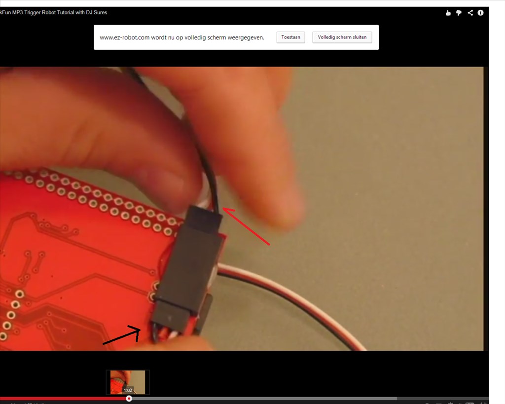
Is This Correct?
i making my mp3 reddy for later use.but seeing the video i got my doubts.
is switshing off the black wire correct?
or is it black on black & white on white
 Ultrasonic Collision Script
— Ultrasonic sensor triggers custom script on object detection; configurable interval & min distance, with optional forward-only trigger for navigation.
Try it →
Ultrasonic Collision Script
— Ultrasonic sensor triggers custom script on object detection; configurable interval & min distance, with optional forward-only trigger for navigation.
Try it →
i making my mp3 reddy for later use.but seeing the video i got my doubts.
is switshing off the black wire correct?
or is it black on black & white on white

Why are you using a mp3 player with your ezb4? You already know the ezb4 has a built in speaker so you don't need a mp3 board... Use the EZB4 soundboard control instead....
am just keeping myself beassy.actully i wanted to solder the ping sensor, but i cant see in the video whits color goes where. so this will not work whit ez-b4?
Solder the ping sensor? Why? To what?
Dude... You don't make sense.... I give up trying to help you.... eek
sorry to hear that.i dont understand why you get upset about one simple question. but i do feel this forum getting colder and colder for me.
thanks anyway for trying.
Hey @nomad18.08, don't be discouraged! Ask as many questions as you need. I think people might be a little overwhelmed lately since there is so much going on and the forum is moving at the speed of light! But I hope nobody's being cold to you. We're all best friends right?
I'm always amused by your posts and your enthusiasm is fantastic. I just want you to keep it up!
Maybe it would help if you can explain your problems and situation more clearly?
hi chrissi
am not discourage.next week i have my special accses point +new laptop win8 as back up pc.so averything goes well. yes my explanation are not very good.its not only the new ez-b am interested. but also the old version to get a better understanding what ez is all about. this was one question +pic,answer is easy to give,i also understand that a , conversation at my low level is not easy for the giants here.
thank you chrissi ,you bin a big support
Without watching the video (as I am unable to right now) I would have thought that the plug is in around the wrong way. There is no real reason that I can see as to why the signal would connect to ground and ground to signal. Not to mention you cannot physically plug some accessory cables in backwards.
Don't just watch the video, find the instructions to the MP3 board and see what it says too. I am sure there will also be a forum post regarding this board too if you search for it.
As for the Ping sensor which you were looking at soldering. Simply use 2 accessory cables, snip off the one end (not the end that attaches to the EZ-B but the other end). Then on one of them snip off the red and the black wires so you only have the white. Now solder the red wire on the one cable to the Vcc of the module Solder the black wire on the cable to the gnd of the module Solder the white of the same cable to Echo of the module Solder the other white cable (on the extension with just the white wire left) to the Trig of the module.
Connect up to two digital ports. Set the ping control port numbers as required and off you go.
There is a video for this too, check EZ-Robot's Youtube Channel for it.
i look for the video
thanks rich