
Asked
— Edited
I2c Questions
I seemed to be having issues with I2C BlinkM's I keep adding the control to the layout and connect the blink M to one of the i2C ports and it disconnects the EZB, every single time. To make sure I have connected the wires correctly could someone point me to a call out that has the break down of the I2C ports, i.e +,-,c,d
Thanks in advance.

Will,
is this one ? https://thingm.com/fileadmin/thingm/downloads/BlinkM_datasheet.pdf
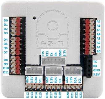
d = I2C SDA c = I2C SCL
source: https://www.ez-robot.com/Tutorials/Files/EZ-Bv4%20Datasheet.pdf
Yup that's the one thanks! Seems I have I wired correctly. Not sure what's happening with the disconnect.
There's ONLY two ways an i2c can cause a disconnect...
It's not wired correctly - which is why it's disconnecting.
the i2c address is specified incorrectly
EZB v4 I2C ports are a single bus, do you have anything else connected ?
Nope nothing else connected. Checked the 4 wires again and they are connected correctly. (Black Neu, red pos, white D, Yellow C) All are addressed at 0x09. This is for Alans eye color control.
Will,
There are a few different blinkm versions and revisions.
blinkm min product info: https://thingm.com/products/blinkm-minm/
EZB is 3.3v
did you used that device before with EZB ?
Hmm good point. The Original Alan was built with the same product. They still work and I can change colors for his eyes using the control for it. But that was 4/5 years ago. Perhaps the product has changed. I won't put too much energy into it. For this project I can just select a color and set that with the programmer, then just Apply voltage .
I agree with @PTP it looks like the BlinkM operating voltage may have changed.
Their pull-up resistor values on the SDA and SCL lines may also have changed. You could try placing low value (330 to 1kohm) resistors on your wiring harness (SDA to VCC & SCL to VCC) to place them in parallel with the pull-up resistors on the board. Putting these parallel resistors in place with decrease the resistance on the SDA and SCL lines pulling them up stronger.