Tonlaar
I’M Trying To Connect An Ardui
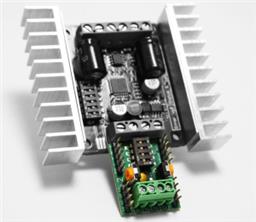
I’m trying to connect an Arduino Nano with the EZ-B v4 to offload some of the work. UART1 and UART2 work fine!
Problem is with UART0 (information is send but corrupted)
Connection:
Arduino GND to EZ-B v4 GND
Arduino RX connected to UART0 TX (first pin), D5 or D18
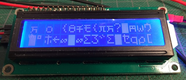
Attached to the Arduino is a 2x16 character LCD (I2C connection) to display (the serial information (also visible true the Serial Monitor) using a simple protocol; 0 (0x30) = clear LCD, 1 (0x31) = start at line 1, 2 (0x32) = start at line 2. All other information is just displayed.
All is fine and Information is displayed correctly when attached to pin D5 or D18.
When connected to the TX pin of UART0 information is sporadically send but corrupted. Touching the wire (on the outside!) changes the behavior of the characters received (more characters but still corrupted)??!!

Hi Cem, I startend this atempt with an Arduino Uno. Same problem. The thing is that UART1 and 2 both work fine. Just the UART0 is giving this problem
Hi DJ, Thanks for your response. I started this exercise with a wire to the digital GND. My current setup is 2 GND wires, one to digital GND and one to the GND of the UART0. Also an extra wire to the 2nd GND on the Nano. Problem is the same :-( What puzzles me is that UART1 and 2 are working fine, so I’m confident the grounds are solid (with UART1 and 2 at least)
Did some more step by step testing.
It seems that the Signal LOW for UAERT0 is not low enough. The lower it gets the better the results
Add the resistor between TX and +3.3v instead of GND... try that
The fact the results change with the bitscope connected still leans toward a broken ground somewhere. The bitscope should be floating and not affect the reading. that's the point of a meter or a oscilloscope for measurement is that it cannot affect the results. The fact that it is affecting the results leans toward a bad ground
Hi JD,
Moving the resistor between TX and +3.3v instead of GND didn't help. Less incoming characters and all incoming characters are corrupted. Removed GND from Digital pin. Connected now is GND from UART0, D5 and D18. As UART1 and 2 are still working fine, ground is fine for UART1 and 2 even using GND from UART0 Any grounding issue with UART0 therefore would be internal to the EZ-Bv4 isn't it?
Maybe ez robot should try and replicate this scenario at there facility. Get it resolved quicker?
We replicate it daily. Many of our robots have arduino, ssc-32 or uart<->usb devices connected. Also, the lidar dev units all connect to uart0. This works for us on a daily basis, which is why i'm at a loss to of why it wouldn't work for tonlaar. All signs point toward a bad ground is the only suggestion i have, even if it sounds like a broken record.
Connecting devices to UART 0 is common practice for us on a daily basis
Long shot, but where are you located? Maybe one of us is close enough to let let you test with another EZ-B and rule out anything wrong specific to yours?