
Tonlaar
I’M Trying To Connect An Ardui
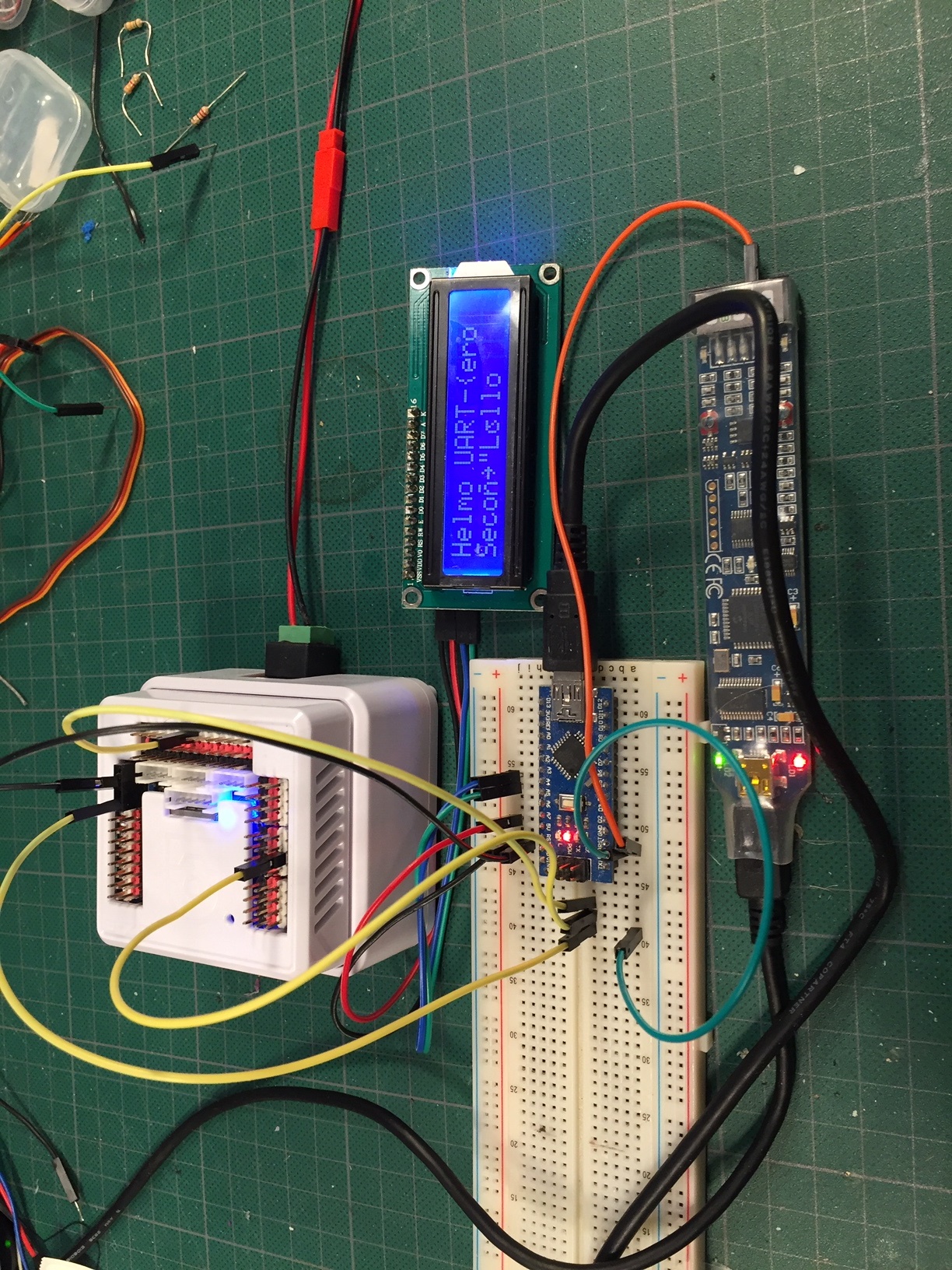
I’m trying to connect an Arduino Nano with the EZ-B v4 to offload some of the work. UART1 and UART2 work fine!
Problem is with UART0 (information is send but corrupted)
Connection:
Arduino GND to EZ-B v4 GND
Arduino RX connected to UART0 TX (first pin), D5 or D18
Attached to the Arduino is a 2x16 character LCD (I2C connection) to display (the serial information (also visible true the Serial Monitor) using a simple protocol; 0 (0x30) = clear LCD, 1 (0x31) = start at line 1, 2 (0x32) = start at line 2. All other information is just displayed.
All is fine and Information is displayed correctly when attached to pin D5 or D18.
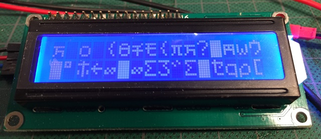
When connected to the TX pin of UART0 information is sporadically send but corrupted. Touching the wire (on the outside!) changes the behavior of the characters received (more characters but still corrupted)??!!

Display of UART-0
Display of UART-1
Display of UART-2
UART-0
UART1
UART-2
Check your wiring to ensure there’s a proper connection. All Uarts are connected to the same chip. There’s no magic between the connector and the micro controller IC. The wires from the connector on the ezb run directly to the microcontroller and use the hardware uart on the IC.
Since uart 0 uses a female connector, I can only assume the wire that is shove into the connector is not making a proper connection. Also, ensure your grounds are connected correctly.
The uart 0, 1 and 2 are all on the same the same IC chip, which is the ezb’s st micro controller.
Also, the voltage scale is different between screenshots of uart 0 to 1 and 2
I checked what I did (not an expert yet with this micro scope). The 1.68V and 2.92V are not the scale but the offset from the zero line, depending on what type of reference is used (MIN, MAX, MEDIAN, MEAN). The scale for all readings is the same, 1 v/Div!
Made new readings with MAX as reference.
Used an "oversized" pin for the UART0 TX wire. Also connected the AURT0 GND with the Arduino GND with a similar wire. Problem is still the same :-(
I understand that, as you say "the uart 0, 1 and 2 are all on the same the same IC chip, which is the ezb’s st micro controller" but the way the signal is presented has to be different as TX UART1 and 2 are routed through digital pins 5 and 18
Could this be something with the pull-up for the TX pin of the uart0 or the fact that uart0 is 3.3v?
UART-0
UART-1
UART-2
Hmmmm... are you really really really sure the gnd’s are joined between the arduino and ezb? Can you show a pic of your physical wiring so I can get an understanding of the setup?
The script keeps displaying the message to the 3 UART's
I can move the green wire between UART0, 1 and 2 to check the results for the different UART's.
The orange wire is for the BitScope Micro.
UART1 and 2 are fine. Only UART0 has the problem that characters are corrupted. (sometimes a few, sometimes all)
Could it possible that the signal for UART0 is just not low enough therefor getting correctly identified sometimes and sometime not?
:loop UARTInit(0, 0, 9600) UARTWrite(0, 0, 0x30) sleep(100) UARTWrite(0, 0, 0x31, "Hello UART-zero") UARTWrite(0, 0, 0x32, "Second Hello") sleep(100)UARTInit(0, 1, 9600) UARTWrite(0, 1, 0x30) sleep(100) UARTWrite(0, 1, 0x31, "Hello UART-one") UARTWrite(0, 1, 0x32, "Second Hello") sleep(100) UARTInit(0, 2, 9600) UARTWrite(0, 2, 0x30) sleep(100) UARTWrite(0, 2, 0x31, "Hello UART-two") UARTWrite(0, 2, 0x32, "Second Hello") sleep(100) Goto (loop)
I got nothing. Looks like everything is attached properly to me.
Could there be an issue with the breadboard? I know you said you have changed the jumpers but maybe there is a bad connection? Have you tried different holes on the breadboard or even a different one? Perhaps you could hook up UART 0 directly and bypass the breadboard.
DJ mentioned before that UART 0 is a female connector. Maybe that connector inside the housing is damaged. You could solder a wire onto the back of the board at the solder joint just below this pin to check it. However I would not recommend this as it would void any help you will get from EZ Robot. Also if you are not good at soldering you could mess something else up. My motto is: No Guts, No Glory but your wallet has to support that. LOL.
You can’t short all three TX lines of each uart like that and get the same voltage during activity. That’s why you’re reading unusual voltages. Because the uart’s that aren’t writing are holding their voltage state - which is causing the active uart to over drive.
Also, take a ground from one of the digital pins, because perhaps it’s not grounding well in the female connector if it’s a bit loose.
Either way though, I can’t think of a reason why the uart #0 would not work for your application. I can’t even imagine a reason.
Unless I'm missing something or looking at the picture wrong I don't think his TX lines of each Uart are shorted on the breadboard. I know little about the Nano and how to wire it. Are you talking about the connections I see at A4 & A5?
I do like DJ's suggestion of running another ground from the black ground pins of the EZB's digital pins. Multiple grounds are always a good ideal in case one comes loose or broken. How about also attaching another ground wire to the other side of the Nano and running it directly to a EZB digital ground pin just to be sure. Bypass the breadboard with a sure ground connection.