elfege
USA
Asked
— Edited
Hmc5883
Hi,
Has anyone successfully connected and used a HMC5883L compass on I2C port without systematically crashing at init ?
I'm kind of stuck and wish to know if I should go on trying again or give up.
Did read former threads about same topics Did find datasheet and Hex address of chip DId use I2Cwrite and Read commands Did use tutorial's script did use everything I can think of. Wires are connected sda to sda scl to scl and then 3.3V.
Let me know if any of you guys have a robot capable to know where it's heading thanks to a compass.
Is there not a more simple compass hardware like with an analog output readable on ADC ? Just asking in case it makes any sense.
Thanks in advance.

i2c is a sensitive protocol and is vulnerable to interference and capacitance issues. The really only way around i2c issues is to use a PCB with small traces, filter caps and smart placement of resistors. Also the type of wire used to connect from the i2c device to the ez-b also needs to be correct. The wire cannot have each +3, gnd, sda and scl merely floating around, otherwise they act like antennas and collect interference. Unless you're using a i2c pcb that has been properly designed by an experienced electrical engineer, it's a tough thing to get working
Jeremie will chime in on his design schematic for the ez-robot test module we created. Of course, due to jeremie's awesome electronic design experience, the ez-robot i2c devices always work.
To this day, i still have not gotten an i2c device to work that i designed myself. So don't feel bad I leave it to the engineers!
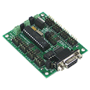
@elfege what breakout are you using? Do you have a picture?
Beakout? Not even sure to know what you are referring to... sorry. Probably the actual hardware, I figure. Here is a link :
JBtek Electronic Compass (3-axis Magnetic Field Sensor) GY-271
Below are the models I ordered for replacement (I think I killed the other one... reversed polarity... but long after I tried using them and in a moment of despair...) I had bought two, though, in case this kind of accident happened. And killed them both... stress
4 of GY-273 HMC5883L 3-Axis Magnetic Electronic Compass 3-5V Blue
And this one, not sure how useful it'll be, but as I was saying, I'm hopeless :
Diymall trademark Mpu-9250 9dof Module Nine-axis Attitude Gyro Compass Acceleration Magnetic Field Sensor
Thanks a lot for your support.
NB : Did I understand well ? Did Dj mentioned that EZB provides a model that is fully compatible with EZB V4? Not sure I got it all though. If so, then I'd love to buy it, but I can't find it on the website.
Thanks Elfege
EZ Robot sells this one in the store.... 4 in 1 orientation sensor
Thanks @RR! Actually the only place to get the 4-in-1 is Brookstone at this moment in time.
@elfege the 4-in-1 has an MPU-9150 on it which has a compass built-in, should be a good fit.
Yes what you have is a HMC5883 breakout board. That's what they call little application boards that usually have a single chip's pins broken out on a PCB. If you like to continue to use the HMC5883 with the EZ-B you'll need to either change the SMD pull-up resistors to a stronger (lower resistance) pull-ups like 330ohms if you don't want to do SMD soldering you can place some lower resistance pull-ups in parallel (via a breadboard or otherwise) with the existing 2.2k pull-ups on the breakout board.
THanks a lot Jeremie, Dj and RR. I saw the product in EZ store little after I had asked my question, but it is indeed currently out of stock. Maybe I'll look into BRookstone later.
About the previously mentioned HMC5883 I received today : This time, using 150 ohms resistors between SDA and SCL on the chip and an old EZB's V3 I got the device to not crash the EZB's connection. However, not joy yet on EZB V4 and this is mainly due the fact, I know, that I didn't really understand all the intricacies sent by Jeremie in his message.
What is the PCB ? Power Cutoff board ? ? I guess not. What are the pull-ups ? To me its a way of working out... And finally, I can't identify the resistors I am suppose to bypass / replace.
And I couldn't find 330 ohms resistors so I tried with 450 and... same : EZB V3 ok, but no joy on V4. oh... did I mension that the data returned by the command print($compassx) is -1 and this whatever direction it's pointing at, so I guess I still have some serious work ahead.
Sorry... I really see how I didn't get much to what you said Jeremie and I don't want to take too much of your time so maybe I'll do some research online because it feels like there's everything I need to know in that message you sent me.
But if you feel like guiding me a little bit more (for instance about where I'm suppose to solder the parallel resistors), I'd be more than happy !
I assumed, though that it was the two little things marked "472" that are located right between the chip and the SCL and SDA ports. SMD soldering = ? Pulling out the two little resistor and replacing them ?
Thanks a lot. I'm learning so much !
ELfege.
Sorry @elfege things got busy and this post slipped my mind.
PCB = Printed Circuit Board Pullups = A resistor used to tie a signal high (i.e. 330ohm resistor from SDA to 3.3V)
You won't need a resistor connected from SDA to SCL.
You will need a resistor from SDA to 3.3V and SCL to 3.3V.
If the pullup resistors on your HMC5883 Breakout board are "472" this means that they are 4.7Kohm resistors. One way to make the circuit work is to desolder those resistors and solder "331" (330ohm) resistors there instead.
Another way would be to take your 450ohm resistors and connect one from the SDA pin to 3.3V and the other from SCL pin to 3.3V. This would place the onboard 4.7K resistors in parallel with the 450ohm resistors which would make ~410ohms. 410ohms should be close enough to 330ohms to have it work.
Thanks a lot Jeremie,
The MPU 9150 seems to workers well. However now I need to figure out how to use it... It looks like the $compassheading doesn't return very consistent data. For example if I turn something like 45 dog left it returns 155 and if, from the same starting point, I turn 45 dog right it returns again 155 . The starting point returns 158 and if I turn 180 set I get something like 112...
Now if I move forward, I don't get the same values again for the same degrees. Basically it's like I can't get a fixed point of reference which is much needed and the very use of a compass...
I was lately trying to combine $compassX values with $compassY values since they differ from the 155 left heading and the 155 right heading. But I'm pretty sure I'm missing something here
Other question : where am I to connect all the other ports on the MPU to use gyro and other variables? And what are the respective functions of these ports ? Init, something-sync, etc. ? (Sorry typing from work on my iPhone )
Thank you so much for your support,
Elfege