tevans
Brazil
Asked
— Edited
Help With Encoder
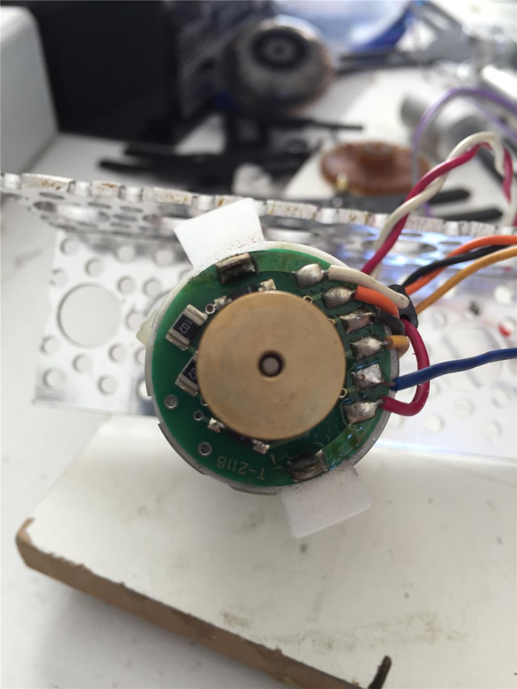
friends.. Can Anyone help me figure out how to wire this encoder ? I can't find the specs , and can't make it work with Kangaroo.. I know that the WHITE is Ground and RED is POSITIVE for the Motor, but don't know witch one is A, B, 5V and Ground for the encoder...

THIS IS ALL PURE SPECULATION BASED ON WHAT THE ENCODER LOOKS LIKE It looks like you have Ground, 5V, B+, B-, A+, A-
I see 6 wires so you probably do not have I which is common.
Ground and 5V should be a single wire. B+ and B- would be twisted together A+ and A- would be twisted together
Again, this is speculation.... To connect to the Kangaroo, I think that you would just use the 4 wires of Ground, 5V, B+ and A+. B- and A- would be the drops but I assume that the A+ and B+ wires are low when the A- and B- are high. This should be sufficient for the Kangaroo as it is looking for High on and low drops on the same wire.
I am going to say it again.... This is speculation based on what I see in the photo.
Where did you get it, make model? Found this pic
https://www.encoderonline.com/Encoder-Pictures/Gif/PullUpWiringNormal.gif
I am probably totally off. Are the white and read wires providing power to the motor?
If the outer wires are providing power to the motor, I would think the wires are as follows for the 4 inner wires. 5V, Gnd, A, B with the 5V and Gnd being twisted together. This is assuming that it is a quad encoder. If it isn't it could be just 5v, gnd, A and I. If it is not a quad, the I signal wire would give you a high signal every time the motor makes a full revolution. if it is a quad, you would see pulses at every tick of the encoder.
ultimately, I think you will have to find some sort of a datasheet to know for sure. What is the brand of the motor or any markings that would be indicative of the manufacturer?
If you don't have the specs and the only option is guessing:
I would pick a multi-meter and select ohms and i would try to find which ones are the phases (A,B), the phases usually have pull-up resistors.
there are two smd resistors 102 = 1K, i would guess those are the pull up resistors.
both pull up resistors are connected to the 5v, so each side of the resistor is connect between them and 5v. Find the common side, and you will find the 5v.
the other side of each resistor is connected to the Phases (A,B), between each phase wire and the 5v there is a resistance of 1K, check that too.
the remaining wire is the ground.
My bet is orange-5v, black=zero, Phases = yellow, blue
Ok folks! I'll try your sugestion and let you know!