Asked
— Edited
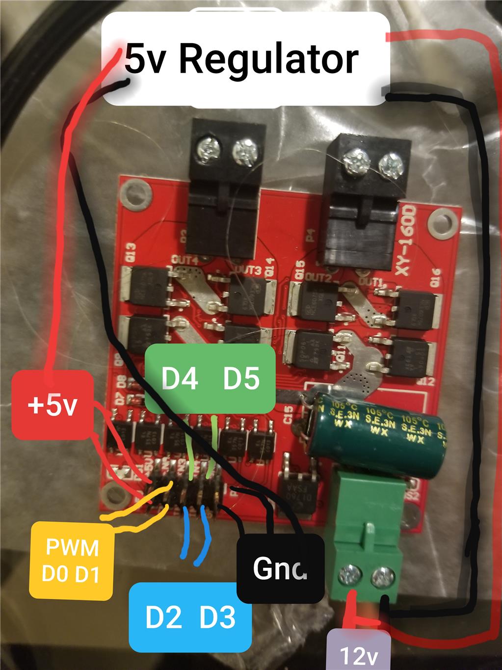
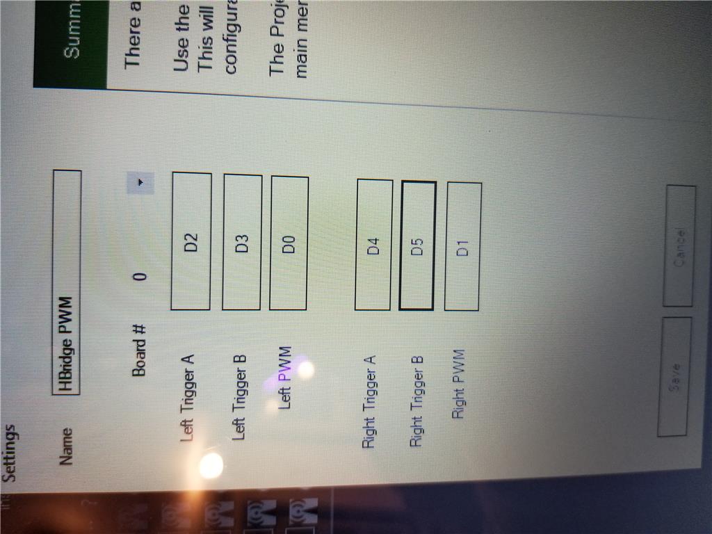
Sorry, this was my first attempt to hook EZ B to a motor controller. I looked up several sources and thought sure everything was set up correctly but it isn't working. See the attached photos please of what I did, and maybe spot what is wrong. 12 volts in from an automotive battery, branched off to a 5 volt regulator. The strange part (to me, anyway... maybe this makes sense to someone more knowledgeable) is this; while troubleshooting, I accidently touched a ground wire to a trigger pin and the motor turned. so I tried them all and applying the ground to each pin caused each motor to spin either forward or reverse as it should if it were getting power.... Any ideas? BTW I triple checked all polarity connections are correct to the relative labels.
P.S. How to attach photos??
Related Hardware EZ-B v4
Related Control
Dual HBridge w/PWM


Hi, Dr._Rudy_Wells Have you got a common ground between the ezb and the regulator supply? As there are no photo's it would help to know which motor controller you are using and which pins were grounded to make it work.
All the best skidroe
hi skidroe
did uou puch in the small white button ?
skidroe
for your second question,here's a video.
Here’s the manual for hbridge skill:https://synthiam.com/Docs/Skills/Movement-Panels/Dual-HBridge-w-PWM?id=16067
From the picture above it looks like the board already has an onboard 5V voltage regulator, so there may be no need for an external one. Check the chip to the left of the 12V input, probably a 7805 or equivalent. The +5V pins on that board are likely 5V out, not in.
Here's the application wiring that I found from the datasheet for that H-bridge.
Note that when you are using the H-Bridge with PWM, you do have to toggle the sliders on the skill's main window to enable the PWM. I'd advise to bring them up to 100% for testing and dial them back when things are working.
I will mark this resolved, but in actuality I have not gotten a chance to re-try this experiment