Asked — Edited

Ezbv4 D12-23 Not Working

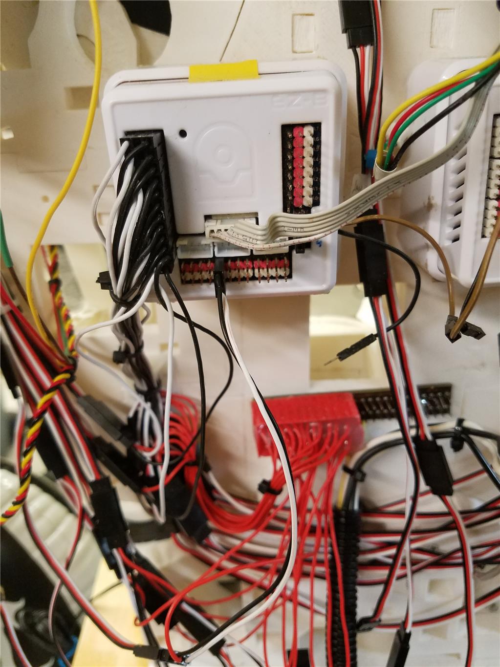
I have 2 EZBv4 controllers that D12-D23 do not work. The first one stop working a few weeks ago and now the second one. I have tried doing a reset with the reset button but that didn't help anything else I can try? if not is just the controller board available?

RichardZ


ARC Pro

Upgrade to ARC Pro

Become a Synthiam ARC Pro subscriber to unleash the power of easy and powerful robot programming

PRO
Canada
#1  

Hi RichardZ,

Were the two EZ-Bs placed into the exact same application? What is usually connected to D12-D23? How are you testing these ports?

You could try taking the EZ-Bv4 enclosure off and re-seating the WiFi board on the main board. Separate the two boards and them put them back together, just like in this video:

PRO
USA
#2  

Jeremie, Sorry for the delay in responding, I was at a county fair showing my Inmoov as a static display. Both EZB's are in the same Inmoov. But the second EZB ports stopped working before I put it in the Inmoov. The InMoov is powered by a 60 amp Dell Server Power Supply. I take the 12v from the power supply and that powers both EZB's. The 12v also goes to 2 - 25 amp 6v regulators that supply power to ALL servos. All grounds are tied together.

I have tried reseating the communications board on both.

RichardZ

PRO
Canada
#3  

Hi again RichardZ,

To test each port you could make a new program and hook up an LED to Ports D12-23 and send a simple signal like a digital high and low? (Just make sure you have the LED cathode to Gnd and Anode to the digital port)

Do you own a mulitmeter? You could use that as well to see if there is a signal at the Digital ports or if power it's getting to the D12-23 Red power pins.

PRO
USA
#4  

Yes, I have a good multimeter. I will do the high/low test first and depending on how that turns out, I will compare D12-D23 sinewave output to a working port with my O'scope.

I will post my results.

PRO
USA
#5  

using the following basic code, I checked each port and had no change on the white (data) pin. 0v


:loop
set(D12,off)
set(D13,off)
set(D14,off)
set(D15,off)
set(D16,off)
set(D17,off)
set(D18,off)
set(D19,off)
set(D20,off)
set(D21,off)
set(D22,off)
set(D23,off)
Sleep(1000)
set(D12,on)
set(D13,on)
set(D14,on)
set(D15,on)
set(D16,on)
set(D17,on)
set(D18,on)
set(D19,on)
set(D20,on)
set(D21,on)
set(D22,on)
set(D23,on)
Sleep(1000)
goto(loop)


PRO
Synthiam
#6  

What was connected to those ports?

PRO
USA
#7  

805BB Servos, and drew power from a separate buss not thru the EZB.

#8  

@rz90208 I could be wrong but I thing @DJ means what was attached to those ports when you did your set(D12,ON) tests....

PRO
USA
#9  

Nothing, I used a multimeter to test each port to see if it was toggling between 0 and 3.3v

negative lead on a ground pin.

PRO
Synthiam
#10  

I did mean what WAS connected when they were working - because what ever was connected must have damaged the i/o circuitry inside of the main ARM CPU. If it was servos, i would definetly check the wiring to ensure there was no short or accidental power being applied to the signal (white) pin. Having separate power to the servos is irrelevant to the signal (white) pin, because the signal (white) is a direct connection to the i/o of the main ARM CPU. There are current limiting resistors on all i/o pins, but that won't prevent the chip itself from being damaged if too high of a voltage is applied to them.

All signs lead to the bottom board needing a replacement

PRO
USA
#11  

Thank you DJ, How do I go about ordering just the bottom board?

PRO
Synthiam
#13  

Before connecting the servos to the new board - can you run through the wiring to ensure there's no shorts or anything?

How are the servos powered? Can you provide pics?

PRO
USA
#14  

Yes, I will post a wiring diagram and some pictures shortly.

PRO
USA
#15  

The red plug below the EZB goes to my 6v buss. As you can see all power wires have been removed from the servo plug and rerouted to the home-made red power plug. The EZB was powered with 12v. I now plan to change that. So the EZB also gets powered by 6v and I will turn off the battery warning.

User-inserted image Wiring.pdf

#16  

According to your PDF schematic you have the hot (+) lead of the 12v and 6v power supply connected to each other. Is this correct or did you just mis-draw this part of your drawing? If you have them tied together then suppurate them. You can't have them tied together. The neutrals (-) are OK to tie together but that may not be necessary either. Grounds and neutrals are strange about how they are wired sometimes and need a little extra attention. ;)

PRO
USA
#17  

@Dave The 6v regulator is a dc/dc converter. it takes 12-24v in and outputs 6v. the 12v is a Dell Server Power supply. I have tied all the 12v leads together and all the grounds together. The 12v goes to 2 - 12vin-6vout 25A DC/DC converters. The 6v then goes to the 6v buss and the 12v also power the EZB. Because of when testing I cooked one 805bb by plugging it directly into the EZB (giving the servo 12v), I am now planning to also power the EZB with 6v and turn off the low battery warning.

#18  

Ahh, OK then. That makes sense. It sounds like you have a very solid and well thought out power circuit. Nicely done. Some people struggle with power circuits.

Just a thought here but could something have burnt out in the EZB ports when you burnt out the Hitec 805bb? You wouldn't think so but ya never know with electronics. Perhaps it's time for a new EZB.

This is a little off your OP but your mention of using a Hitec 805bb and powering it through the EZB struck me. The Hitec 805bb is a nice servo but it's considered a heavy duty servo. Be careful about powering servos through the EZB. If your have a lot of load being channeled through it and feeding power hungry motors you can easily brown out the EZB and cause a reboot. The 805bb only pulls 830mA but that's at idle. When it starts up the amp draw will spike and then smooth out but will pull many amps when lifting a load. Then add a few more big servos to the EZB and you're really asking a lot of the well built components inside of the EZB trying to keep a smooth power supply it it's own circuitry. I always make it a practice to power motors and servos around the EZB unless they are small and doing light duty. :) Another advantage of powering servos and motors around the EZB is that if something happens to the motor you won't send a voltage surge back through the EZB. Fuses in the right places are your friends.

PRO
Synthiam
#19  

The 12+ and 6+ are connected together in the diagram - sure you're not feeding +18 into the servos? The 6v battery seems to have 3 connections in the diagram.

PRO
USA
#20  

@DJ I do not use any batteries. All power supply. Guaranteed only 6v (I have tested it). I do have a 8000MAH 7.2v LIPO I could use to power the EZB. Do you think that is a better solution?

@Dave I have molded a plug using hot glue that all the servo power wires are in, so all of InMoov's servos are powered from the 6v buss not the EZB. How I did that was: Removed all power wires from my 6" servo extension cables. plugged them into the 6v buss. Took a few pieces of scrap 3d printed plastic and wrapped the around it. Then sprayed it with PAM cooking spray (so it does not stick to the buss) and pumped it full of high temp hot glue. Now I have a plug and nothing will short on the otherwise bear pins. Dave, I also think that is the only explanation of what happened. The servo when powered by 12v shorted in some way and possibly (just guessing) applied 12 to the signal pin.

#21  

Hi DJ, According to rz90208 the 6volt power source in his diagram is a 12v to 6v dc-dc buck power converter not a battery. It would have + and - power in, then same wiring out (sorry, of course you know that. LOL). According to the drawing it looks like he's running his neutral for the servo through the EZB.

rz90208, Pam for non stick glueing. Never heard that one. Nice tip, thanks! Do you need to wash the Pam off so it does not rot and smell? Hot glue makes for a good stress relief between the solder pads and wire also. ;)

Adding another power source won't hurt but won't correct anything you have going here. It will add a dedicated power source to the EZB and anything powered through it and remove load from the other power sources. However if your adding a battery to a non battery robot it will be a battery to keep track of and powered up.

PRO
USA
#22  

@Dave, After the glue sets, I trim off the excess glue and using a toothbrush and a spray bottle of alcohol I clean up everything. And you are correct, the servo neutral does go to the EZB. Do you see a problem with that?

#23  

I added an edit to my last post about adding a battery to a non battery robot. In short I think you'd just be adding a complication and maintenance issue. Just stick with power converters. Just make sure your existing power supplies are wired correctly and can deliver the amps needed.

As far as running the neutral through the EZB; that should work OK but I'd add a dedicated neutral wire along with the power wire to the servo. Best practice. Keeps your power delivery system in line along with a common neutral to the EZB. That way you'll have all the needed connections and also have multiple paths for the unbalanced load incase you loose a connection or break a wire. ;)

PRO
USA
#24  

Ok Dave now you got me thinking. I am going to make another buss for the return (ground) just like the 6v buss and remove the servo return from the EZB.InMoovWiring2.pdf

#25  

Ya, you can't go wrong with that setup. ;) Have fun!

PRO
USA
#26  

Received my new bottom boards but want to try and prevent the issue from happening again with the new boards. I am considering putting in blocking diodes inline with the signal wire. (1N4004 have over 100 in my parts bin)

EZB ------- |<----- Servo

This should prevent voltage going back to the EZB if the servo would short out.

Comments, suggestions.

PRO
USA
#27  

@rz90208,

What you want to do is called flyback diode.

There are typically flyback diodes on the internal servo control board. You shouldn't need them externally.

If you "really" want to isolate the servos, you will need an Opto-isolator for each servo, some H-bridges use them.

https://www.sparkfun.com/products/9118

tutorial: http://www.electronics-tutorials.ws/blog/optocoupler.html

That is a bullet prof solution, what ever happens in each side does not cross to the other side.

Don't forget you are dealing TTL levels, you are isolating "TTL" levels, a cheap solution to protect your EZB ports (although there is a 330 ohm resistor between the the micro-controller port and the the EZB pin) is a Logic Level Converter circuit.

tutorial: https://learn.sparkfun.com/tutorials/logic-levels

if there is a short circuit, you replace the LL circuit versus replacing the EZB.

Bi-Directional (Low <-> HI): https://www.adafruit.com/product/757 https://www.sparkfun.com/products/12009 https://www.adafruit.com/product/395

or DIY version (single direction): https://www.adafruit.com/product/1787

Note: Both the opto-isolator or the Logic Level require a 5V source to drive the high side (Servo's ttl input signal). You can use a BEC or step-down circuit to obtain 5V from the servos power supply.

PRO
USA
#28  

@ptp DJ informed me. The servo signal inputs go direct to the CPU, no buffering what so ever.

I have a drawer full of lm324 quad operational amps from when I built my CNC control board.

EZB --- 3v --levelshifter 5v --- lm324 ---- Servo

Servo (805BB) can handle the 5v TTL signal on the signal pin or do I need a second level shifter?

(was hoping to shortcut and just use a diode so it could be inline, no additional boards.)

I like your solution better, as you said bullet proof.

PRO
Canada
#29  

@rz90208 there is a current limiting 330ohm resistor between each servo pin and the MCU. This protects the MCU I/O pins in a large amount of cases, except over-voltage. Unfortunately, a diode likely wouldn't work due to the voltage drop across the diode, taking a 3.3V signal and subtracting the diode's 0.6V voltage drop would leave the signal at 2.7V which is very close to limit for detecting a "High" signal for most chips.

I do like @ptp's idea of an opto-isolator or level shifter. A simple transistor could do the trick as well.

PRO
USA
#30  

After rereading the thread, DJ did mention the 330 ohm resisters.

So after reading the links ptp posted. (Thank you ptp). I can just use the level shifters low voltage side toward the EZB and do not need the lm324 at all.

EZB --- 3v-LS-5v ----- Servo

for the 5v I can get that from my 6v supply and use a couple 7805 regulators. Can I get the 3.3v from an ADC voltage pin or just use an LD1117V33 regulator off the 6v supply?

PRO
USA
#31  

keep it simple...

Lower side: get the 3.3V from the ADC bank, both EZB/Iotiny have a very good DC/DC circuit.

High Side: get the 5V using a regulator, you only need a few mA to drive the servos logic, so whatever you have on hand i believe is ok.

bear in mind if you use raw regulator (e.g. 7805) is always a good idea to have capacitor on the output side (stabilize), check the datasheet.

PRO
USA
#32  

Thank you my Cylon friend. Have the 7805 on hand and ordering 10 - Adafruit TXB0108. That will cover both EZB's I have in my InMoov and a few extra.

#33  

@rz90208

You state "The InMoov is powered by a 60 amp Dell Server Power Supply". I had a couple here lying around (45.5 amps) and decided to mod them for my power supply. My GOSH, when turning on it sounds like a jet taking off ... lol. The fan is unbearable! I then modded the fan circuit to only turn on low but it's still too loud for the small room my robots are in. Too bad, because if it wasn't for the noise they are cheap, high quality and very powerful.

Was wondering if you ran into this problem?

(Figured I could high-jack this tread as it is so old.)