Asked
— Edited
Ezb V$ And Camera Dimensions?
I did a quick search but could not find anything on the dimensions for both the ezb V4 and the new camera un-housed. Is there a schematic floating around that has already been posted? I need it to make modifications. In particular I need a side view and measurements of the side view of the camera and pcb its attached to. Thanks in advance to any links or info.
Edit, dang cant change the typo in subject field!

There are some details in a topic floating around somewhere but it would take some searching to find.
From memory I think it's around 3cm by 2.5 by 2.5 (Camera)
The V4 board is 5cm by 5cm by 3cm (info on the product page)
OK so it didn't take much searching... The V4 camera details are in this topic and my dimensions above were correct.
Thanks Rich!
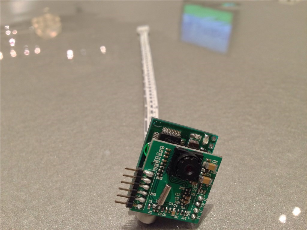
Could one assume this is the proper orientation of the camera? If the pcb is 3 x 2.5 x 2.5 cm I just need to know the proper orientation, so the image is upright, not sideways or upside down.
@fxrtst
Yep the way the camera is pictured there is the proper orientation for an upright image.
While I'm here I figured I'd give you more accurate dimensions of the un-housed camera:
The camera board itself is: 2.2cm x 2.2cm The adapter board behind it is: 2.2cm wide x 2.72cm High
I don't have the depth dimensions written down yet but I'll get those soon and update this thread. With a depth measurement you'll have to keep in mind that the JST connector on the back and the Camera lens on the front are the maximum points that stick out, the camera board to adapter board depth will be much less.
Thanks. Just what I wanted to know. Great help. Any idea the measurement from the top edge of the board to the center if the lens? Also what are the 6 pins to the left on the board for?
@skater_i10 , anymore proper set of cad files or the like of the camera out of its shell? I'm at a critical point in final designs on my upcoming product release and I need a top down view with measurements like edge of pcb to center of camera, etc. Any chance of releasing that kinda of info here? Also are the pins along the side going to be in the final product?
Thanks in advance
Hi @fxrtst
The pins along the side won't be in the final product, they were just for there for testing. As for CAD files we don't have anything drawn up yet but I will see if I might be able to work with Cory to get some thing for you. Would a 2D drawing suffice?