
okidey
Netherlands
Asked
— Edited
External Power
Hello everyone, how are you?
I know there are several topics around relating to modifying the EZ-Board for use with an external power supply. I just need to check to confirm that I understand correctly before I start modifying the board.
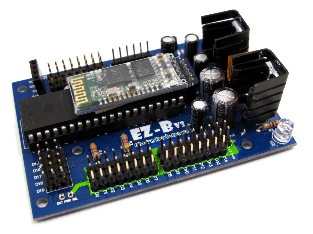
As I understand it, the ports D0 - D14 power is originally supplied by the board, coming from the lead between ports D19 and D0 as shown in the picture below..right?
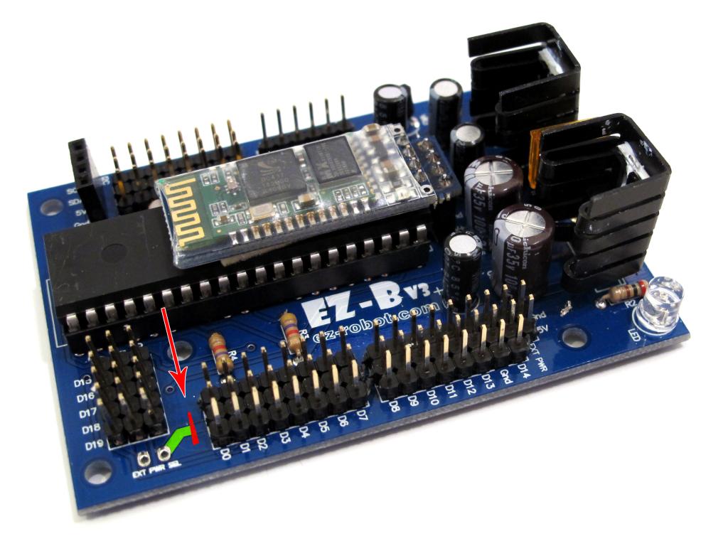
So, I will have to cut or interupt that lead to isolate those ports from the board's power like so..
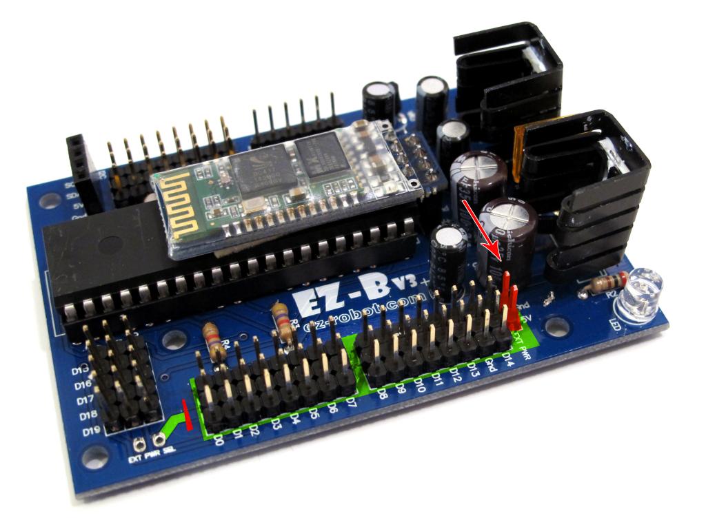
Then I will simply need to reastablish power by connecting the leads of the external power supply to the last 2 pins next to port D14, as indicated by the red arrow, correct?
Do I understand all this right? Kristian.

Kristian, you got it all except cutting the power lead. Look on the bottom side of the board where the EXT PWD label is. The trace between those two pins is to be cut. Not the trace that you had marked.
Goodmorning DJ. Thank you, I'm glad I checked lol. For the sake of illustration and clarity I will add a picture showing the correct way to cutting the power lead.
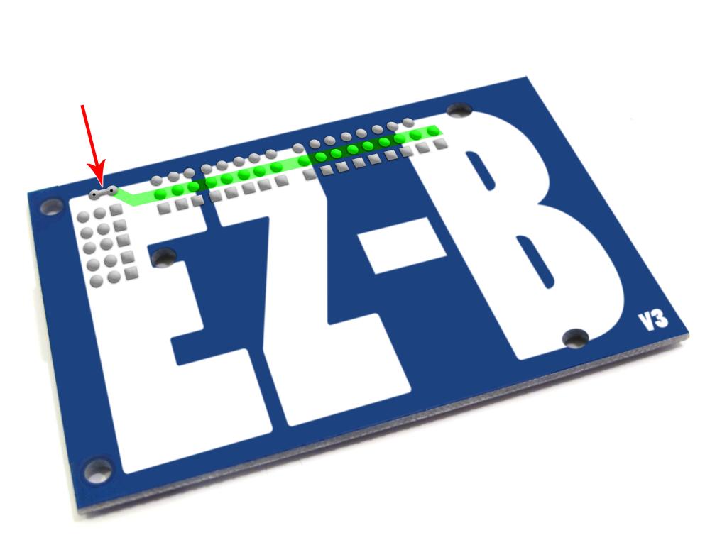
I could not find a picture showing the bottom side of the board, I hope this representation will do the trick.Thanks again, I can get back to work. Kristian.
Dude, that's an awesome drawing! Yup, that's the trick!
Thanks for the illustrations btw, i'm going to use them in a how-to for others ... Full credit to you of course!
Thanks haha you are very welcome! Go right ahead, if you ever need any other illustrations or graphics I'll be more than happy to help. This was a rather fast one for the purpose of getting a clear picture. But I'm good with graphics and if you ever need anything, I have loads of time.
After building new 4 DOF arms for my robot Captain Ann Droid, I have exceded my requirements to power the arms directly off of the EZB3. You can follow my plan, Captain Ann Droid thread, on how I was planning to build an external power source using servo extensions and a voltage reg. (8-40 volt to 5 volt) and tying the grounds together. I then found this old thread showing how to modify the EZB3 for external power. This would save all the servo ext wires modifications. My question is there any disadvantage to using the above modification, vs. the servo ext. build? Has any one performed this modification and how did it work? Thanks in advance. Steve S
The only disadvantage will be that ALL 20 ports will be subject to the modification.
Robot-Doc, Thanks for the response. That is a good question, does the mod only affect the ports D0-D14, as Okidey thought, or does it affect the 5 ports also on the small side of EZB3? My eyes cannot follow the traces. It would be nice if not all ports were affected. Steve S
I think this Will cut the power flow only on d0 to D14... If I use this trick, the heat will decrease on the board? Mine get very very hot in less than 10 minutes...