
RoboticsMaster
USA
Asked
— Edited
Controlling Specific Leds Besides The I2c Hardware?
Is it possible to use special leds such as 7 color blinking leds within the ezb programmer, besides? using the blink i2c hardware? What I was planning to do was to possibly use servo extension wire to wire the leds, and then plug them into two ports, take pins D4 and D13 for exemplars. Is there any program to control these leds to make them work in a correct function? Thanks.

As I understand the 7 colour LED it has three pins, Vin, GND and a Mode. The Mode pin selects the color that is to be displayed after the initial power up sequence. The modes change when momentarily shorting the Mode pin to GND.
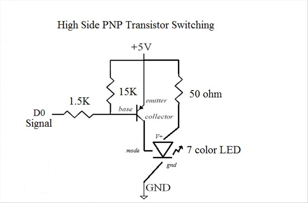
To create the circuit, a resistor is required in series with the LED Vin pin and the EZ-B Digital port's 5v pin. The basic formula to find the resistor value is:
Resistor ohms = (Vin - LED FV)/LED Current
Or
51 = (5v - 3.2v) / 0.035
AKA
Resistor value 51 ohms = EZ-B 5v - LED FV 3.2v / LED Current 35ma
The catch with using the EZ-B will be switching the modes... as far as I know you can NOT use the EZ-B signal line directly as that would be like shorting the LED Mode pin to 5v and not GND, but you could probably use a low power switching transistor controlled from the EZ-B signal pin that acts like a switch between the Mode pin on the LED and the GND.
Then used the SetDigital control to "pulse" the transistor thus act like the momentary switch between the LED Mode and GND... and therefor control the colors and flashing modes.
That exhausts my practical experience so without further research and testing I do not know the type of transistor to use, but perhaps someone else might? Or perhaps a different way of accomplishing this?
True, very true. Thanks for the advice.
It would help if you posted a link to the datasheet of the device you are referring to also
After more digging around I was able to find some info where others had hooked up these LEDs to other microcontrollers... one person used a 2N7000 N-Channel MOSFET to simulate a momentary switch... but no clear wiring examples where given.
Also, here is the data sheet I was using for reference.
I am looking around to see if I can find one of these LEDs locally before I order some off of ebay... they look fun to play around with.
That screenshot does not include any control information for the LED. Somehow there must be a signal that the LED accepts on the "mode" pin. Maybe the mode pin simply requires a bit of voltage to simulate a "switch". If so, than that is easy Connect the mode pin to a Digital pin on the EZ-B and cycle through the modes using the Digital control, or the Digital EZ-Script commands
But, i'm simply speculating regarding the MODE pin. you'd need to find out more by looking at the datasheet.
Yes, i google'd and MODE is just a momentary switch of +5 to cycle through the modes.
https://www.seanliming.com/Docs/Articles/MSGBB557TA_7_Color_LED.pdf
So simply connect the MODE pin to a digital pin on the EZ-B. Use a Digital Control or a Digital EZ-Script command to turn on, and off that pin. That will simulat a "switch". Voila
Thanks @DJ. I edited the datasheet to highlight the mode switch function... and it matches what you located. However the switch is meant to drop the MODE to GND... not 5v, so simply using the EZ-B signal may damage the LED? As per other articles I have looked at, there needs to be additional circuitry to allow a micro-controller pulse to act as a switch between MODE and GND.
I did suggest the transistor, but am not experienced enough (yet ) with electronics to layout the exact transistor type and wiring along with any required resistors or capacitors to clean up the electronic "switch".
Any additional advice or circuity layouts?
Thanks guys! Now project SIHRO will have professional looking led eyes! Oh, and if you want to see what my project is, refer to this site:https://letsmakerobots.com/node/33846