
Johnnybib
Canada
Asked
— Edited

Hello!
I am wondering if it is possible to control an electromagnet with an ez-b. All I would need is to turn it on and off. The electromagnet I would use would just be a simple iron nail wrapped in insulated copper wire. How would I go about connecting this to the ez-b so I can control it?
Thanks!
For a simple TIP 120 circuit, see this thread http://www.ez-robot.com/Community/Forum/posts.aspx?threadId=3050 unfortunately there is a lot of nonsense from a now banned former member polluting the discussion, just read the posts by Rich.
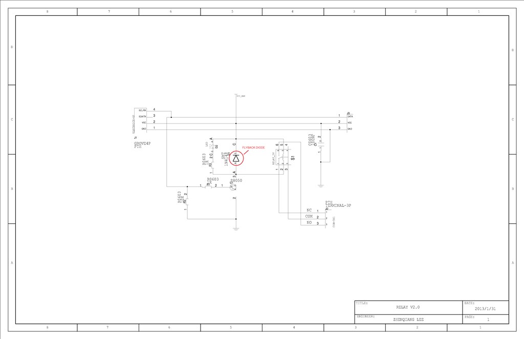
Several users utilize this relay, which is comparable in price to the parts you would need for a TIP 120 and is plug and play: http://www.robotshop.com/en/electronic-brick-5v-relay.html
Alan
Could I use the 7.4V LiPo battery that would power the ez-b to power the electromagnet as well or would I have to use a separate battery?
Also would a 9V battery work here? It would be nice to use a 9V since they have those connectors.
EDIT: I do not know how this got below my previous post with the circuit diagram.
When enabled the relay will close across COM and NO which will complete the circuit. When disabled it will open across COM and NO which will break the circuit.
Provided the electro magnet doesn't require any resistors etc. and works fine with the supply given there will be no problems.
A TIP circuit would also work (as Alan suggested) but if you have no or little experience and don't have many components the relay board probably works out cheaper and better.
Alan
This is often called a "flyback diode" and will prevent arcing between the contacts of the relay when it opens, as well as, suppress transients (voltage spikes) in other parts of the circuit. Since you are using a separate 9V supply for the magnet, that should not be much of a problem for the EZB4, but a large spike can cause electromagnetic pulses to be induced into other circuits as well.
The size you will need would be determined by the current flow going into the electromagnet when in operation. As a rule of thumb, the current capability of the diode should be at least the same, and the voltage would be based on the voltage of the power supply (9V in this case).
It's impossible to advise you on the proper size needed since I don't know the current flow. However, a 1N001 will probably do. A 1A ,1N007 would be a pretty safe bet but larger size. Neither costs very much. Connect the diode as close to the electromagnet as is feasible. Be careful to observe the polarity as indicated in the diagram above (reverse biased).
To know if the diode is working a simple test is to look at the contacts of the relay without the diode in place and see how much arcing there is when the relay opens. Then see what it is with the diode on place. Using a flyback diode will also extend the life of the relay contacts. Be sure to actually solder it in place when you are happy with the location. Simply wrapping the leads of the diode will not always provide proper protection. Especially later on as oxidation builds up between the diode leads and the wire.
As an FYI, a small capacitor can give you much the same protection when using an AC circuit. Also, this same problem can occur when putting a relay in a circuit. The coil of the relay should have a flyback diode as well. The relay board you are about to use, however, probably already has one in it so that should not be a concern in this case.
There, probably more than you ever wanted to know. My fingers tend to get verbose.
Am I correct in labeling the flyback diode? If that is the flyback diode then I wouldn't need to solder an extra one on like you suggested right?
Also would there be any way to prolong the battery life? The electromagnet is pretty much a short circuit so it would drain the battery extremely fast. Would putting a resistor between the magnet and the battery help?
Thanks!
Very good. Yes, that is the flyback diode for the relay coil (only). I'm not sure if you understand, however, it will not protect you from your electromagnet's spike as well. You will still have to put in another one for that.
And yes, adding a resistor in series with your electromagnet will reduce the current flow to your electromagnet and prolong battery life considerably. Even 100 0hms can help a lot. If the electromagnet is considered a short circuit, then 100 ohms would limit the current to 9v/100 =0.09A =90ma. Of course the "pulling" power of the electromagnet will also be considerably reduced. The power that such a 100 ohm resistor would have to be able to handle in this circuit would be 9V x 0.09A =0.81W. So you would need a 1W resistor (at least).
The thing to keep in mind about electromagnets is the strength of the magnetic field is dependent on both the current flowing through it and the number of windings it has. The more windings, the greater the magnetic strength. Though that does not go on forever since the more the number of windings the greater the distance the outer windings are from the core. That weakens the magnetic field at the center. Magnetic strength falls off by the square of the distance so even a small change in distance can have a large impact on the strength of the magnetic field generated. That's why very thin wire is usually used for the windings. Of course such thin wire also limits the amount of current they can handle before burning out. There's always a trade-off.
Also, as you probably know, the electromagnet should have a metal core. Steel is often used. You want a core that will concentrate the magnetic field generated by the windings but not remain magnetized when the power is cut. It becomes a compromise.
Having said all that, you may be better off buying an electromagnet as opposed to making one of your own. These often have a much higher resistance than a home made one with many more windings. Usually the windings will have a high enough resistance so as to not need a series current limiting resistor, yet still provide a strong magnetic field. You can often find a such electromagnet in the core of a relay. That's basically all it is; an electromagnet which pulls in a switch. The core is selected so as to not retain a magnetic field when there is no current flow as well.
Such an electromagnet will also require much less power to run because you don't need a series resistor. You can get an idea of how much power that is by touching the resistor when in operation. It will be warm, maybe hot depending on the physical size of the resistor used. That's totally wasted power and will run the battery down sooner than need be.