
Hi all,
I thought I'd throw this out to our talented community and see if anyone has some good ideas on how to build a self tensioning motor mount. It's not really a plea for help but more of an idea swap looking for different ideas.
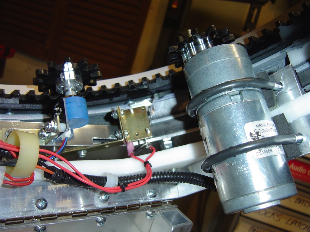
Here's the application and need; I have a lazy Susan that is turned by a set of gears. The outer gear is attached to one ring of the Lazy Suzan and the inner drive gear is attached to a shaft of a motor. Because of human error while building the rotations are a little off so when the gear turns and gets to on one side of the rotation the drive gear sits nicely and firm in the teeth and there is no play or slop. When it rotates the other way the drive gear will be a little out of the teeth and allow a little slop in the gears and the Lazy Suzan will wiggle a little. To illustrate here's a couple pictures of my setup:
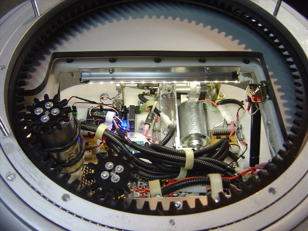
Well, I want it to be nice and tight all the way around the rotation so there is no play anywhere when the robot stops at any given point. My idea is to make a tensioner of some kind that will be either spring or gas strut loaded and pushing the drive gear into the main gear. This way when the gears rotate, the teeth of each gear will always be completely engaged.
The drive motor I want to mount is about 4" long and 2" across. My first idea is to make this out of either a large hinge or a piece of aluminum plate with a hinge attached. I can then use a "U" pipe bolt to attach the motor to the hinge (kinda like I have my existing motor mounted in the pic above). I'd have to set it up in a 90 degree angle so the "U" bolt wouldn't hit anything when it moves and let a spring pull the "Door" part where the drive motor and gear is attached into the main gear. I'd have to get the spring or gas strut strength just right to keep the rotation from stalling or the gears from jumping teeth.
Anyway, that's my first thought on a design. If anyone has a different idea, a design change to my plan or knows of any supplier already selling something like this please chime in.
Thanks!

As troy said, I believe the problem is an off-set outer gear. This may sound fuzzy, but you could set the drive motor on some kind of moving platform/shaft, with (don't laugh) weak elastic bands pulling it forward when needed. Then when the outer ring is in the correct place, it will pull it back so it will always be in the correct place. I might be able to sketch it if needed.
Great ideas everyone and thanks again for the kind words about my B9.
There's a lot to think about here. There's a lot of wisdom in seeing if I can just refit the gears so they run true and tight. I think the gear that's off center is the drive gear on the motor shaft. I had no way to center it on the hub exactly other then my eyeball before I screwed it down. I think I'll start there first. The other idea that really looks good to me is Herr Ball's idea of the self closing door hinge. I think that is real slick, self contained, easy to install and also adjustable.
To be honest I really don't understand the rubber ideas. If it's used in a clutch then it must be a good idea. I'll have to look into that one some more. I would really like to stay with using the parts I have but could rebuild if it's the best way
The gear set I'm using is sold by a building club vendor and commonly used in the big B9's and the full sized R2-D2's so they should do nicely. I think it's a good idea to follow the suggestion given and contact Andy or other builders and ask for advice on how to get the gear set to run true.
Thanks again for offering your insights and suggestions. If you have any other ideas please share.
What I see Dave is the gears don't mesh properly... You output gear's splines (off the motor) are too small/narrow (or too far away) and rounded... They don't fit the lazy Susan's angular ring gear... If you can find a matching angular drive gear then you won't have to concoct an elaborate motor/hinge/spring doohickey to get rid of the slop... Contrary to what someone else mentioned here in the thread, gears need to mesh at a fairly tight tolerance for smooth quiet operation... I am no expert, but I have torn apart enough bike gear boxes to know how gears work....I confess I didn't read all the posts on here, but Is possible to move the motor closer to the ring gear? That might all but eliminate your slop....
Hi Richard,
Thanks for the input but these gears are a matched set. They fit perfectly. The edges of the small drive gear are beveled to help avoid any collisions with the teeth edges. Your right though the problem is that the drive gear is to far away from the main gear. Problem is when it gets to the opposite side of the rotation it's nice and tight.
Dave -
You mentioned it earlier: your gear/donut is off-center: loose at one extreme and tight at the other.
It will probably be easier to move the drive motor than the entire torso; or just use one of the "elastic" setups mentioned.
Our friend, See the Sloth and his R2D2 droid probably have the kind of setup you are looking for. I linked a couple picks from his R2 build site, so all credit to him.
I've worked the past few days on bringing this idea to reality. I ended up using Herr Ball's idea of using a self closing adjustable door hinge and it turned out great! Before I go feather I gotta say Thanks to Herr Ball! This has turned out to be one of the coolest additions to my robot.
It was very easy and cheap upgrade and it makes all the difference in my waist turning mech. There is absolutely no play in the gear anywhere on the rotation and I have the added safety feature of this also being a clutch of sorts. If something blocks the torso rotation the spring will give and the teeth will simply jump each other;
I simply went to Ace Hardware and bought a 3" adjustable Self Closing door hinge (about $15 use for a set), a small 1/8" piece of plate aluminum and a couple U bolts that fit around my motor. The aluminum plate was cut to hold the motor and attaches to one wing of the adjustable door hinge with the U bolts. I had to cut a spacer out of some Acetal plastic because the bottom of my gear motor is smaller then the top. Have a look at the Video I took and the pictures I snapped and enjoy.
Again, Thanks for all the help on this one. Couldn't have done it without all the ideas!
That is a great job of engineering to resolve a discovered dilemma. What a crew on this EZB forum.