Asked — Edited
Resolved Resolved by Rich!

Basic Led Light Question

Hello again. My current question regards LED lights. I just want to turn them on and off. I searched the forum and all of the forum responses regarding LED lights were much more involved than the answer I need. I gather you use a servo control to do it. I've tried several different servo options, but none have worked to do what I need. I just want to turn them on and off. I have them connected to a digital connection D06. Maybe I should use an analog connection? Thanks.


ARC Pro

Upgrade to ARC Pro

Elevate your robot's capabilities to the next level with Synthiam ARC Pro, unlocking a world of possibilities in robot programming.

United Kingdom
#1  

Nope, keep them connected to a digital Signal pin and the ground. Use the Digital Set control to operate the LED You can also use script commands;

Set(D6, On)

and

Set(D6, Off)

Or to flash it at half second intervals;


:loop
Set(D6, On)
Sleep(500)
Set(D6, Off)
Sleep(500)
Goto(loop)

This will only work for one LED per port. Any more will be too much current draw for the EZ-B's signal pin and will require a transistor switching circuit.

#2  

Thanks Rich. I tried the Digital Set. Didn't work. The lights remain on and will not turn off in either the red or green setting. Maybe the problem is that it is a light bar with 6 LEDS? If I understand you right, it only works for one LED per port.

#3  

Hmmm. What is happening is that the lights turn on whenever I connect them to any port. Even an unassigned one. That is strange but maybe an indicator to what is going on?

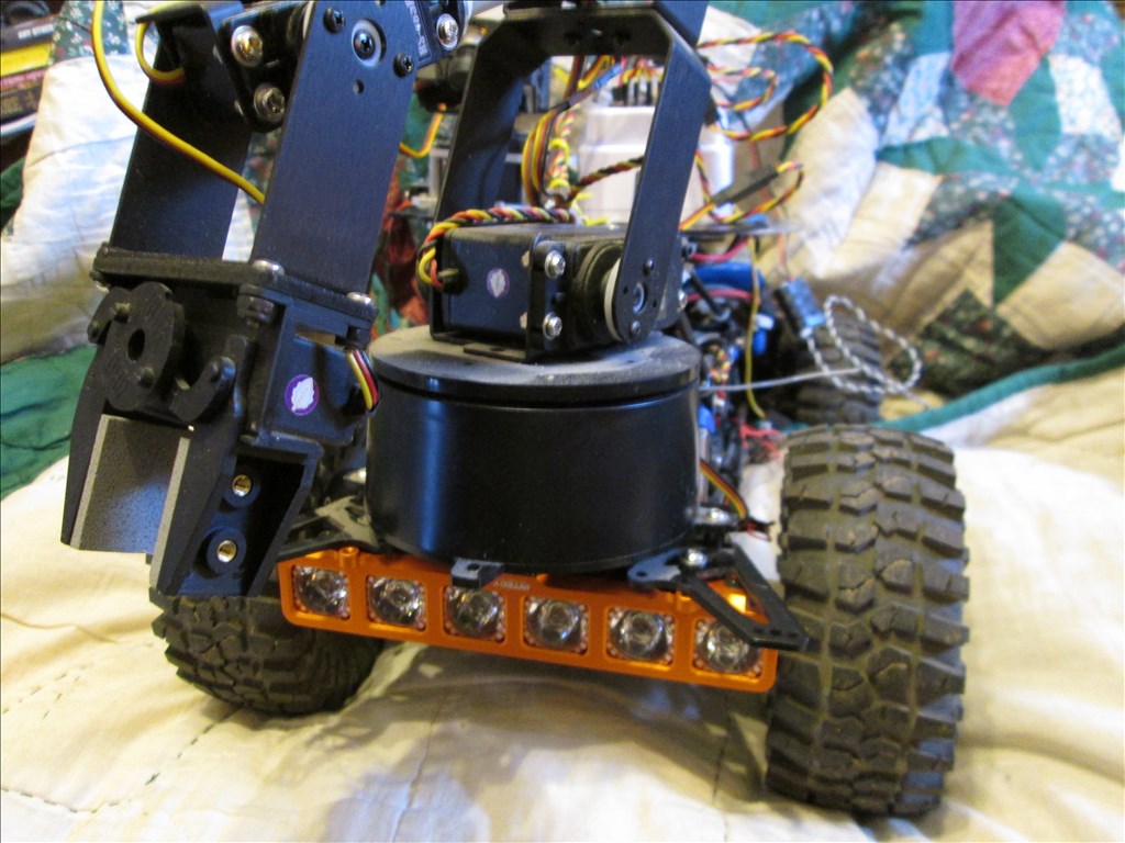
The 6 LEDS are going through a light control unit. The control unit does not have any settings, just connections for the LED array.

#4  

How do the leds come wired? What kind of plug and what are their voltage requirements, mA's etc........ You may not be able to drive them directly from the ezb... The signal pin pushes 5v but can only supply about 20ma.. The power pin equals battery voltage that you are using... So if you're using a 7.4v battery be aware your LED light strip is getting that voltage too...

#5  

It sounds like you are connecting to the ground and VCC port (black and red) not ground and signal (black and white). As Richard said, the VCC port will provide whatever voltage you are giving your EZ-B. Without a resister or voltage regulator, that will burn out most LED's, so the fact that yours are just staying on is lucky.

(@Richard R - signal pin on the V4 is 3.3v, not 5v. V3 had a 5v signal pin).

Alan

#6  

Thanks Richard. I don't know if I can answer your questions but I will try. The LEDS are from a Tamiya RC light kit (TLU-01) and are 5mm LEDS. I don't know the voltage. Yes the power supply is from a 7.4v 2 cell Lipo. The LED are connected with a small white connector (don't know the proper name) to an Axial "Simple LED Controller" which has two inputs for lights and one output that connects to the EZ-B. The LED controller commonly handles 6 LEDS. For RC the LED controller is typically connected to the receiver which is, I believe typically powered by 5 vdc through an electronic speed control (ESC).

The lights are on, so the power seems adequate. I just can't figure out how to turn them off. I'm thinking maybe the problem is in the LED controller, but I'm not sure.

#7  

Hey Alan. Thanks. You are right on again. The connector is from the LED controller is black and red. That must be the problem. Now, how to fix it. I have a bunch of servo extension wires. If I solder the LED controller black wire to black and the LED controller red wire to white it should work? I'll get right on it.

#8  

From the precious little documentation available (http://www.tamiyausa.com/pdf/manuals/53909ml.pdf) it doesn't look like the controller actually does anything except provide regulated power to the LEDs. the only control is the power switch on the controller itself, which turns on or off the LEDs when you provide power.

You would be better off cutting the LEDs off and just connecting them to digital pins on the EZ-B (of just buying LEDs directly, they cost just a few cents a piece).

Alan

United Kingdom
#9  

If the current draw of the LEDs is less than 20mA connect the red wire to the white signal pin and the black wire to the black ground pin.

If the current draw is 20mA or above you will need to use a TIP122 Transistor switching circuit and possibly a voltage regulator.

Control will be the same for either option and as mentioned previously.

#10  

Thanks guys. Well, I tried the black/white connection as suggested and no soap.

Actually Alan I am using the 6 white LEDS from the Tamiya kit, but the AXIAL LED controller (AX24257). The plan was to have the ability to illuminate area my robotic arm was working with.

User-inserted image

I may just have to power them with an external battery, but I wanted to remotely control the on/off with the EZ-B.

#11  

If you want them all controlled simultaneously, then Rich s suggestion of a TIP120 transistor is the way to go. Simple simple circuit to build. Allows you to use the EZ-B digital port to control switching of higher voltage or current.

Alan

#12  

Hey Rich and Alan. I appreciate the suggestions. The TIP120 may be a simple simple circuit, but it is way out of my league. I can solder two wires together, but after that it is pretty much plug and play. I don't think the current is a problem, but may be wrong. All of the LEDs do illuminate when connected to red and black, but I guess the draw may be too much for the EZ-B.

As an alternative, maybe I can power the light bars (there will be two - the 6 LED at the rear and a 2 LED at the front) with an external battery and run the power through a switch. Can I control a switch like that with the EZ-B? I guess it would have to be a digitally controlled switch.

Canada
#13  

Try controlling a toggle switch with a servo

#14  

You can use a relay or a mosfet as a switch... simplest would be a relay like this 5V relay

#15  

Controlling a switch from the EZ-B is exactly what the TIP120 circuit is for. It essentially is a digitally controlled switch.

It would be nice if someone manufactured them pre-wired into an inline switching circuit, but the parts are so cheap and the circuit so easy to do that I don't think they would make any money.

send me your mailing address (my email address is in my profile) and I'll see if I have time to throw one together for you this weekend (might even get to it tomorrow night).

I was planning on making one for myself for a similar reason, so I can just make 2 at once and mail one to you. My soldering skills are not great, so it will probably be a little ugly, but it will work.

Alan

PRO
Canada
#16  

A relay circuit would work as well, there's a bunch of small boards online (plug and play style) that only require you to hook up signal, voltage, and gnd wires in one side and your positive supply wire on the other side.

Just make sure you get one with a transistor onboard, I believe in the past @Technopro purchased a board that didn't come with one.

United Kingdom
#17  

The TIP circuit is very basic to be honest and isn't difficult to make. It'll also improve your soldering skills (it did mine!)

You wont be able to run 6 white LEDs from the signal port, white LEDs are usually higher current than other colours and sometimes you can't even run 1 on the signal current.

You could use a toggle and switch via a servo but that's a bit rough and personally I'd steer clear of it.

If you want a plug and play option you could use an Arduino Relay board (just search ebay for one). If you were in the UK I would send you a TIP circuit, maybe someone in the USA will offer that?

#18  

Quote:

maybe someone in the USA will offer that?

@Rich, see post #16.... I just did.

Alan

#19  

Wow! Thank you guys. Great ideas and help from all of you on this board. Alan, I will take you up on your offer. I'll send you an email.

Craig

#20  

Problem resolved mostly by Rich, the TechGuru, and Richard. I also appreciate Wolfie's and Jeremie's responses. I can only select one, so I will be using Rich's design with Techguru's kind help.

Craig

#21  

OK, How did you resolve the problem in the end. There were many options given to you. Curious minds like to know. :)

#22  

I mailed him a TIP120 circuit, based on Rich's tutorial but wired inline instead of strip board.

Alan

#23  

Yes. And thank you again Alan. When I receive the circuit and wire it in, I will report back on this thread. I'm sure it will work fine. When I said "I can only select one" I was referring to needing to report that the problem was resolved, but I was only allowed one choice of name, when in fact several folks helped me. I had received two email reminders to "close out" the thread. While I am going with the circuit that Rich designed and Alan built, the other suggestions were helpful to me as well. I am new to this, and helpful information is golden.

#24  

I received the circuit from Alan and hooked it up. Works fine for my LED display using the Digital Set function. Thanks Rich for the design and Alan (thetechguru) for making the circuit for me. Now on to my next step. This forum is very helpful. Guess y'all know that already.