Asked — Edited

Back Again With The L289n Question

I am back again with the same problem with the motor driver. First, I have been experimenting for the past 3 weeks! without sucess! I have watched the L289N tutorial at least 2 dozen times. With out sucess. I really need some assistance here!!!! I have a lot of time and money invested in my robots. I think it is a reasonable expectation to have them operate correctly!!

I have exactly the same problem with "Gizmo" and "Servo" (Servo is a Radio Shack Robie Sr.)

  1. The robots will move forward and reverse as they should; but left and right are reversed!

  2. I assume that the H-bridge control is read as; top arrow is forward; bottom arrow is reverse; right arrow is right; and left arrow is left. Have I assumed correctly?

  3. The configuration I started out with is as follows: IN1 to D18 IN2 to D17 IN3 to D16 In4 to D15 PWM to D19

Since then I have tried every configuration possible. ie; changing around all of the triggers, one at a time. I've tried reversing the motor output leads from side to side and reversing the motor leads at the screw terminals. Believe me when I say I have tried every configuration!!!!! I find it difficult to believe that I have gotten 3 of the motor drivers that are bad. What are the chances of that??????? Since I have the same problem on both of my bots leads me to believe that I am making the same error on both! So, I"m asking for some help here! I have 2 robots sitting here that I can't proceed with until I get this problem resolved. I would REALLY appreciate any help in resolving the problem. I'd be so very dissappointed if I had to just let my projects sit on a shelf unused. As I always do; I thank anyone in advance for any assistance.


ARC Pro

Upgrade to ARC Pro

Unleash your robot's full potential with the cutting-edge features and intuitive programming offered by Synthiam ARC Pro.

PRO
Synthiam
#1  

Your configuration needs to be reversed if the controls are reversed. It's impossible to understand how you have the motor polarity or hbridge settings per robot configuration. That is why there is a confit button in every control. With the confit button, you can customize settings.

Good luck!

#2  

Perhaps I am stating my question in the wrong manner. Does ANYONE have a configuration that works with an Omnibot and/or Robie Sr. and the L289N motor driver? If so, would you please share it with me? I've tried everthing I know to try. Again; I have tried changing the signal wires to every possible configuration as well as the motor output leads. I have watched the motor driver tutorial over and over. I have also tried looking at the configure (question mark) multiply times. Any help would be greatly appreciated. I'm stumped!

#3  

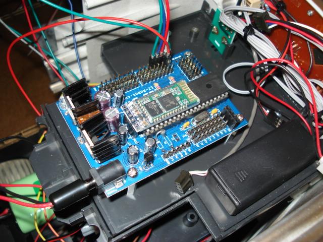
I will post some pictures later today as my camera battery is charging. In the meantime here is a description of my hookup.

Main battery positve goes to a European style terminal strip. Red lead goes out to power terminal on the EZ-B and to the VCC on the L289N Main battery negative goes to terminal strip then out to power terminal on the EZ-B and to ground on the L289N.

Red wire from +5 volts on the L289N to the +5 volt pin D0 on the EZ-B

Right side motor wires (Yellow and Orange) on my Robie Sr. goes to the L289N motor out pins 1 & 2 (Yellow wire to motor out #2, Brown wire to motor out #1 Left side motor wires (Red and Brown) on my Robie Sr. goes to L289N motor out pins 3 & 4 ( Red wire to motor out #3, Brown wire to motor out #4)

L289N IN 1 goes to EZ-B pin D1 L289N IN 2 goes to EZ-B pin D2 L289N IN 3 goes to EZ-B pin D3 L289N IN 4 goes to EZ-B pin D4 EZ-B signal pin D0 is assigned as PWM and set to 75%

H-Bridge configuration is: Left trigger A = D1 Left trigger B = D2 Right trigger A = D3 Right trigger B = D4 clicking on right arrow makes robot turn left clicking on left arrow makes robot turn right

What have I missed?

#4  

Try this in your H-Bridge Configuration: Left trigger A = D4 Left trigger B = D3 Right trigger A = D2 Right trigger B = D1

That's what fixed my same issue & it's what DJ means by "Your configuration needs to be reversed"

Canada
#5  

There should be no ground going from your main supply battery to the L298N.

You should have the following: (Assuming you have a 12V source for main battery)

+12V (Red) to Vcc L298N +5V D1 to +5V L298N GND D1 to GND L298N WHT D1 to IN1 L298N WHT D2 to IN2 L298N WHT D3 to IN3 L298N WHT D4 to IN4 L298N

I'm at work so I can't confirm wiring for motors. Of the top of my head I had Brown/Red one side and Yellow/Red the other side.

Cheers!

#6  

@ Lumpy:

Thank you very much for your reply. It is most appreciated! I will try the configuration you are suggesting and see how it works. I will still try to get some pics posted later today.

#7  

You HAVE TO run a ground from the battery to the L298N! If you only hookup the ground to the EZ-B, your drive motor ground current will be running through the EZ-B circuit board, these sized motor will still run but it's very bad practice. The whole point of a motor controller is to burden it with the motor current, not the EZ-B.

Canada
#8  

I don't see it being hooked up in DJ's video.

The only ground connected is from the EZ-B D15 to the L298N in his video.

#9  

Your right, his new video (I just watched it) does show it like that (though his diagram at synthiam.com/Tutorials/Hardware.aspx?id=25 shows it the correct way). But it's still a bad practice to propagate. Sure it works fine with small batteries & motor (like the AA batteries & little motor DJ used in that video), there's not allot of current flow.

Now imagen using big SLA batteries & motors that draw the L298N's max, 2.5A each Now your running 5A across the EZ-B ground plane & input connector, then add 4 amps in servos running off the EZ-B, now your running 9A through that ground plane / connector.

Now move up to a worse scenario, a 10A per channel (30A momentary) H-Bridge (like Josh has on Jarvis) with some scooter or windshield wiper motors that draw say 5A driving / 20A stalled) + servos... Now your running 14A through that Ground plane / connector, but wait it'll get worse if your Bot runs into something & stalls the motors, now your tryin to run 44amps through that ground plane.

That's what I mean by bad practice. While it may work (with lil motors), it's not proper DC wiring & could cause someone to kill their EZ-B (or worse, start a fire) if they upgrade to a bigger bot / motors / H-bridge without understanding how current works.

Canada
#10  

I hear ya.

So where would your ground the 5V feed? In the schematic drawing it doesn't show a ground from the EZ-B to H Bridge for the 5V side.

#11  

OK. Here are some pics of my hook up. Hope they are clear enough to see everything. I have put my battery ground back on the L289N. I did try the hook up Lumpy suggested and it made no difference. Still have the same problem. User-inserted image

User-inserted image

User-inserted image

User-inserted image

User-inserted image

User-inserted image

User-inserted image

User-inserted image

User-inserted image

#12  

The ground is the same everywhere on the EZ-B (& should be everywhere on your Bot), meaning the ground at input connector is the same as every ground pin. Connecting both the motor controller & EZ-B's power input ground together at the power source does the job.

Sometimes connecting a ground from an EZ-B gnd pin to the motor controller, in addition to power grounds, can help clean up a signal issue to the motor controller, but can also cause a ground loop, so try it without first. Also, some motor controllers have separate inputs for motor ground & logic ground.

Also, be sure the L298N's lil white button is OFF, which disconnects the L298N's onboard 5V voltage regulator, since the EZ-B is providing the 5V. My L298N acts erratic if that button is on & the 2 5V regulators are interacting.

#13  

Please try this: In your H-Bridge Configuration: Left trigger A = D4 Left trigger B = D3 Right trigger A = D2 Right trigger B = D1

That's what fixed my same issue & it's what DJ means by "Your configuration needs to be reversed".

#14  

@ ndavid79: I'd like to also thank you for your input. Believe me. I sincerely appreciate any help from community members. I will try reversing the configuration. Another thought. The motors should run in either direction, however, I have tried reversing them and it had no apparent effect on the problem. I've also tried every H-Bridge configuration i.e. D1, D2, D3, D4 as I could, hoping to find the problem. Could it end up being some weird configuration such as D4, D1, D3, D2??????? A quick reality check. How many possible configurations could 4 wires contain??? I would think it would be 4 squared, or 16 possible configurations. Input please. Again thank you. I will be watching this thread for more suggestions.

#15  

Based on you bots behavior, forward & backward being correct but turning being reversed, a straight reversal of the pins in the settings like I suggest should correct it.

If everything or just one motor was reversed, an odd combination would be required.

Canada
#16  

Robotz,

I also found that disconnecting and reconnecting whenever I make a setting change helps. That was what happened when I was having issues.

Now I just reconnect, pop the PWM slider to ON (full up) and away she goes.

Ndavid79,

Which is on? Which is off? I'm guessing down is off? No documentation came with this little bugger.

"Also, be sure the L298N's lil white button is OFF, which disconnects the L298N's onboard 5V voltage regulator, since the EZ-B is providing the 5V. My L298N acts erratic if that button is on & the 2 5V regulators are interacting."

#17  

I believe out/up is off. Or you could just remove the whole switch, which will permanently disconnect the onboard regulator. I think I'm gonna do that when I get my RAD tracked telepresence bot back together

#18  

The L289N board I have has a red LED which indicates that the +5 volt regulator is on,At least thats my understanding. I will continue to try different configurations. Hopefully with determination on my part and suggestions from other builders here in the community, the problem will be resolved. Unfortunately, even after this problem is resolved, it will be on to the next, which is camera tracking. Again, thank you all.

#19  

The LED will light whether it gets power from the onboard regulator or the EZ-B. To really test whether that switch is on or off, you have to disconnect the 5V wire between the EZ-B & L298N (or remove power from the EZ-B, but I wouldn't advise this method as the EZ-B will try to draw it's 5V from the L298N's miniscule regulator & the EZ-B's 3.3V regulator might not be powered at all), while supplying battery power to the L298N's VCC, then observe whether the LED is on or off.

#20  

@ Lumpy and nDavid79 and all others Just to help keep mis-communication at a minimun I'll review my trouble shooting from the beginning.

           Original configuration:

L289N Vcc directly from my main battery ( 7.2 volts, 3800 mAh Ni-MH) L289N ground directly from main battery.

IN 1 to EZ-B D15
IN 2 to " D16 IN 3 to " D17 IN 4 to " D18 PWM to " D19 signal pin +5 volts from Pin D19, +5 v pin

H-Bridge config. Left Trig. A = D15 Left Trig. B = D16 Right Trig.A = D17 Right Trig.B = D18

Result: Clicking top arrow made robot go forward " bottom arrow made robot go in reverse " Right arrow made robot go left " Left arrow made robot go right.

2nd configuration : All setting and connections same as above except H-Bridge config was reversed; as follows: Left Trig A = D18 Left Trig.B = D17 Right Trig.A = D16 Right Trig. B = D15

Result: same as above;

Note: Must come back later and continue this post.

To Continue:

Other H-Bridge configurations I have tried: Left Trigger A = D1 D4 D3 D2 D1 D4 Left Trigger B = D3 D1 D2 D1 D2 D3 Right Trigger A = D4 D2 D4 D3 D3 D2 Right Trigger B = D2 D3 D1 D4 D4 D1 Tried changing the PWM to EZ-B pin D0 signal pin And EZ-B +5v volts on Pin D0 +5 v pin. I have tried running PWM at full speed on all these configurations. There may be other configs. I didn't try, but all of these resulted in basically the same reversed directions. I've tried taking the ground off of the L289N from batt and ran from EZ-B. That did'nt work either. I feel fairly confident that I have tried just about every combination that "should" have worked. If some one sees something I've overlooked, PLEASE feel free to point it out to me! The only thing I havn't tried is changing out the L289N to another one. I do have one in "Gizmo" however, so I'm going to try swaping it into "Servo" and see if it changes anything. I'll post the results of that after I try it. Anyone have any other suggestions???? Thank you. Lloyd

Canada
#21  

Robotz,

I'll rip apart my Omnibot tonight and confirm wire to wire and post pics.

It's working good left/right/forward/reverse.

#22  

@ Lumpy : That would be great! I really appreciate yout time and effort. Lloyd

Canada
#23  

Robotz,

Here we go.

My Exact wiring. Current setup as per DJ's video. (Currently no GND to Main Source Battery)

EZ-B D15 -> IN1 EZ-B D16 -> IN2 EZ-B D17 -> IN3 EZ-B D18 -> IN4 EZ-B D19 (Signal) -> ENA + ENB

L298N Out1 -> Omnibot Yellow L298N Out2 -> Omnibot Orange L298N Out3 -> Omnibot Red L298N Out4 -> Omnibot Brown L298N White Switch -> UP (Off)* L298N +5 -> EZ-B D19 +5V L298N GND -> EZ-B D19 GND L298N VCC -> +12V (Source Battery)

ARC Settings -> See pic below.

  • White switch confirmed (Up=Off, Down=On +5v)

User-inserted image

User-inserted image

User-inserted image

User-inserted image

User-inserted image

Hope this helps!

#24  

Today update on the L289N motor driver problem.

I have 2 EZ-B boards. I had board #0 in "Gizmo", and board#1 in "Servo" Today I swapped them out. Now Board#0 is in "Servo" and Board#1 is out of both.

I checked my laptops device manager. Board#0 is on COM3 & 4, Board#1 is on COM10 & 11. The device manger says both boards are operating correctly.

I have 2, L289N motor driver boards. Both have been tried. Both give the same end result.

I removed everything and started all over today. First I tried lumpy's suggested configuration as above.When the main battery ground is removed from the L289N, it does not work at all! I reconnected. I then tried the configuration. Result: All four(4) directions were reveresed. I then reversed the H-bridge configuration to:

Left Trigger A to D15 Left Trigger B to D16 Right Trigger A to D17 Right Trigger B to D18

Result: Foward/ reverse are correct. Left/Right are reversed. Note: this takes me back to EXACTLY where I was in the very beggining of this mess!!!!

Once again; I understand that clicking on the TOP arrow in the H-bridge Movement Panel is FORWARD? Clicking on the BOTTOM arrow is REVERSE Clicking on the RIGHT arrow is TURN RIGHT Clicking on the LEFT arrow is TURN LEFT. IS THIS CORRECT, can anyone confirm please? I will also mention that the speech commands for movement DO NOT work either, and yes I've tripled checked that the speech recognition commands were worded correctly for code. Speech command for FORWARD will work periodically. All others do not! Would it be a fair asessment to say that I have pretty much tried EVERYTHING as far as troubleshooting? Does ANYONE see anything I may have missed? Does anyone have any other suggestions? @ DJ : At this point I would hope you'd agree that I have been very diligent and through in my efforts to troubleshoot and resolve this issue. I further hope that you might agree it is time for some assistance from you. I honestly don't know what else I can try. Your help would be greatly appreciated.

#25  

Robotz012248,

Did you ever get the H-Bridge setup to operate correctly? I never saw an update, so I thought I would ask.

Smiles,

Dane