
Danger!
An Electronics Question
I have an electronics question that I hope someone can help me with. The B9 robot has two lights on the chest that flash back and forth. He also has twelve lights that flash independently a little farther down on his belly.
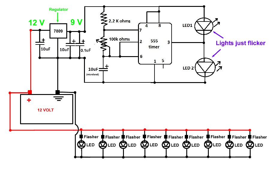
For his "Belly Lights" I bought twelve LEDs that each have a tiny voltage regulator and flasher built into a chip right in the wire. I guess that there is also some sort of diode as well. The wires are both black and they can be hooked up either polarity with anywhere from 5-19 volts. I just put them all in a parallel circuit, hooked them up to my 12 Volt battery and they worked perfectly.
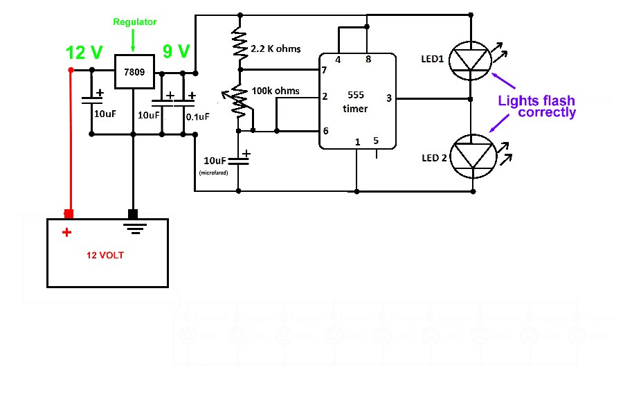
For his "Chest Lights" I found a circuit on the internet to make them flash back and forth. It was designed for 9 Volts. I put it together and tried it with twelve volts. They just flickered. It was too much voltage. I added a 9 Volt regulator and some capacitors, and it worked perfectly.
Here is the problem. If I hook the chest light circuit up to my power source (a 12V battery charger at the moment, not a battery- I don't know if that makes a difference) it works great. As soon as I connect the Belly Light circuit to the charger The chest lights begin to flicker as if they are getting 12 Volts again. I am not sure if they are jumping up to 12 V or if they are flickering for some other reason, but it doesn't make any sense to me. They a two completely separate circuits. I cannot see how adding one to the charger would affect the other one. The charger puts out ten amps; it is not an amperage issue. They are mounted in a fiberglass torso. They share a common ground at the source, but there shouldn't be a ground loop going through the body of the robot. I am just confused.
I did also hook up his simulated neon. It is an array of LEDs that flash when hooked up to a sound input. The chest lights work when that is on, but they do seem to speed up when that is lit up briefly. Again, I am not sure why the chest light circuit is affected by other circuits being connected to the same power source. I haven't even started hooking up motors, etc.
I have included the schematics any feedback would be appreciated.

@Danger! First let's eliminate the charger as a possible cause. Hook both circuits to the battery. See if that makes a difference. Some chargers are not a "clean" source of DC voltage. They can be fine for charging a battery but could induce noise (AC ripple) if used to power some types of electronic circuits.
Unless Im off base here (as I can often be) the 7809 reg can only supply 1A. The added LEDs are too much load for it I think. Datasheet
After a second look (EDIT: I was wrong about the reg circuit. I read it wrong) but I see what youre trying to do. Im still looking.
In your post you said that the belly lights can be hooked up in either polarity but also said that they had a diode in it as well. Can you give us a link to them or it's datasheet?
With that being said, I agree with rgordon. Eliminate the charger as the cause first. (I really gotta stop skimming when I read posts) eyeroll
Thank you for the suggestions guys. I am away for work until Friday, but I will try hooking up the battery this weekend. I dragged the robot up to my third floor apartment to show him off for my Christmas Party last weekend, but the very heavy, deep cycle, marine battery is still in the basement; Otherwise I would have used that in the first place. I do not know a lot about electronics, but I can follow a schematic enough to build the board that I made for the flashers. When I look at it, I cannot figure out how it works. The two lights that flash alternately seem to be in a series. It seemed to work well enough when it was wired up by itself though. I guess that not knowing how it works in the first place makes it difficult to figure out what went wrong with it. After I try the battery, I'll let you know if it worked. Thanks again.
I wouldn't have thought that 2 LEDs, a few resistors, a cap and the 555 timer chip would draw anywhere near 1A to be honest, and since that is all which is using the regulator circuit I can't see the regulator being the problem here.
The 555 timer can accept 12v so you could do away with the regulator and choose the correct value resistors for the LEDs so it will run on 12v. This would eliminate any issues that the regulator circuit may cause. The 2.2k and 100k resistors are what determine the speed at which the LEDs flash so if 12v makes the LEDs flash too fast just change these to slow it down. Eliminating the regulator would point the problem being with the flasher units built in to the other LEDs.
You could always just use an ATTiny microprocessor or modify something like the Evil Mad Scientist Larson Scanner (it's open source).
Thank you for the feedback Rich. I would have responded sooner, but I was on the road, and my phone froze when I tried to post. I agree with you, amperage is not the problem. I tested both circuits using a transistor battery for hours without it showing any signs of draining. You are probably right about taking the regulator out of the circuit and increasing the value of the resistors. The original schematic called for a 50K pot. Even at 9 volts it flashed too quickly. I doubled that and got it about to the right speed. I guess I should try to figure out how high the other resistor should go to operate it at 12 volts. I still cannot figure out how a separate circuit is affecting it, but I suspect that there is some sort of back-feed going through the regulator.
With Christmas coming up so quickly, I am not sure when I will get to experiment with it, but I will call this resolved because I know see a better option that will probably work. I appreciate the input from all three posters, but I would have to say that Rich's post was the most helpful.
Thanks again, and Happy Christmas to all who celebrate it. (Happy Wednesday to the rest of you).
Danger, I have an already built alternate flash unit built by a B9 club vender. It's designed just for the large chest lights. You can have it for just shipping cost if you're interested. let me know
Thank you Dave, that is generous of you. I will try to add a bigger resistor to mine and see if that works. If not, I may take you up on that. Forgive me if I sound stubborn, but after picking up the parts, and assembling what I have so far, I hate to give up on what I have started even if I can get a free replacement. It's just a pride thing. I am sure you understand.
@Danger! I totally understand where you are coming from with that last statement as I'm the same. Although not just a pride thing, an educational thing too
If it is something to do with the flashing LEDs backfeeding you could throw a couple of diode in there to stop that.