
ftlum
Activating A Switch
Hi All.
I'm working on making a full sized Dr. Who K-9 robot and need some help on how to activate a couple things with the EZ-b.
It's going to have a laser pointer in the nose, and I'm planning on taking out the push button switch and somehow activating it instead with the EZ-b. How would I do this?
There'll also be a USB-type powered digitial picture frame to activate. I imagine the same solution could be used for this too.
A little more complicated is a car antenna (it's extends his suction cup probe). There are 2 type of antennas as I understand. A semi-automatic one which I believe needs to revere polarity to retract, and a fully-automatic one which retracts when power is cut off. How would I wire both of these types (I'm not sure which is better)?
thanks in advance,
Frank

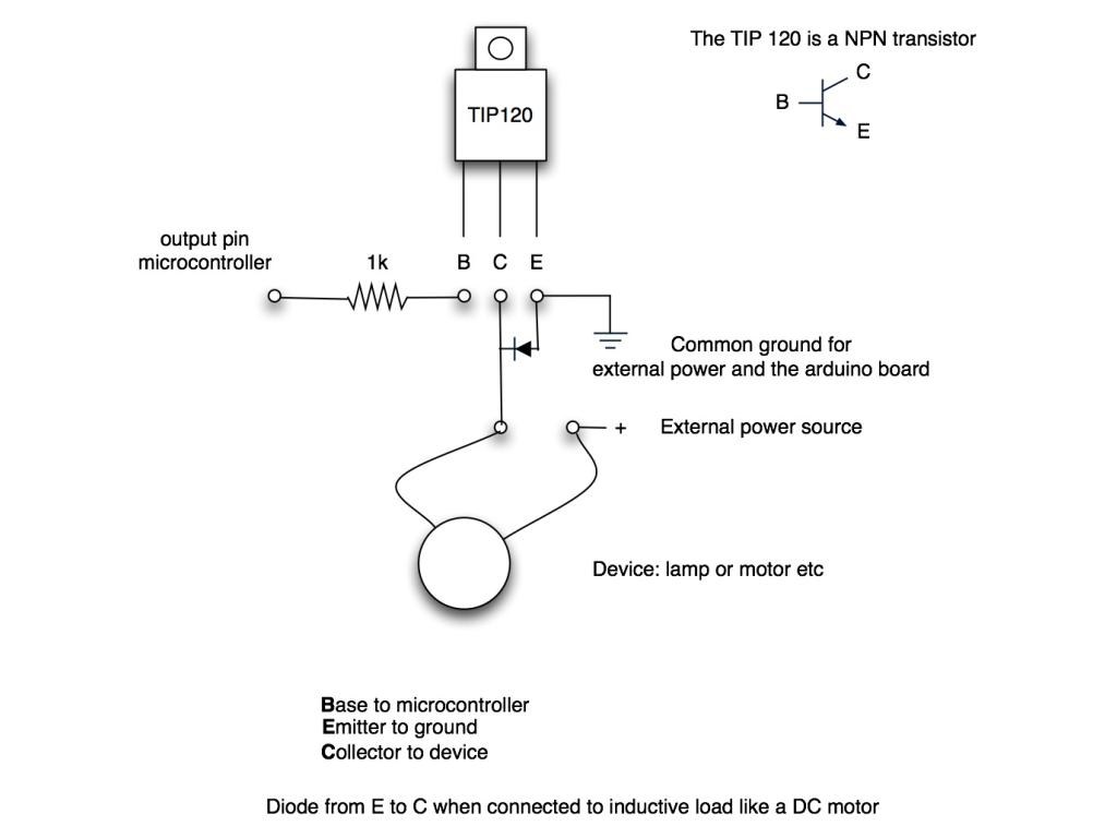
You can use a TIP120 transistor as a switch from one of EZ=Bs digital ports. here is a diagram of how to wire it. I use this to work my lights and other circuits.
Bret's example is an elagent one and I have many of theses in my robot. However it does require soldering and a small project board. If you dont want to do all that you can buy a small relay board built for microprocessors. Search Amazon or eBay. The Robot Shop may have them also. They come in all sizes. Plug and play. something like this:
www.amazon.com/SainSmart-4-Channel-Relay-Module-Arduino/dp/B0057OC5O8/ref=sr_1_1?ie=UTF8&qid=1355588069&sr=8-1&keywords=arduino+relay
Thanks!
To activate a semiautomatic car antenna to a given distance and retract it back to "zero", I was thinking of using an H bridge. Would this work? From what I've read, you need to reverse the polarity of those motors and I'd need to keep track of the position of the antenna. I'm also using a sabertooth 2x12 for my wheels, but I presume there'd be no interference.
I'm guessing a 2 spdt relays could be an alternative, but it sounds like the h bridge is already set up to do what I want.
Do I have things right and how can I keep track of the antenna distance with either method?
Thanks again,
Frank
Actually, I don't use a small project board for the TIP 120. I solder on my leads and put heat shrink tubing over them. Then I put a large piece of heat shrink tubing over the whole transistor and wire leads and shrink that down. It basically looks like a big fuse with wires coming out of it. Then I just zip tie it where ever I want. It's quick and easy. The problem I have found with using relays is they use more voltage. But they are definitely quick and easy. And probably look more professional on the install. They also cost some money and the transistor method is super cheap.
So on the antenna, do you want to be able to control how far out it goes and comes in? Or is it just going out to a fixed point and then retract back to starting position?
I'm not sure if a hbridge can track position accurately. Could you not use a standard servo, position 1 being fully retracted and position 100 being fully extended (may need some kind of gearbox or linkages). It would certainly give better accuracy.
I may be wrong and hbridge may have the ability to track but I've not come across that action on my 4 wire hbridge, it just has the movement panel...
Also, I plan to do what Bret suggested with the TIP120 (122 in my case, cannot source 120s here in the UK). I do have a breadboard on it's way to test it first but soldering the TIP122, resistor and diode "inline" covered with heat shrink and tied together nicely will take less space and be way cheaper than making up a small board (am I looking in the wrong places or are project boards and PCBs expensive in the UK?)
I also think a servo is a better option, but if he doesn't want to take apart the power antenna I can see what he is trying to do. I would also replace the antenna motor with a servo - would take some modification - but I do think it would be the way to go, and it would use a lot less of the DO ports on the EZ-B.
It'd be nice to control the antenna range, but it's not critical. I understand that a fully automatic antenna just goes all the way up with power and retracts without power, so I'd think one of these relays could do that.
I'm not sure how hard it'll be to put in a servo. The housing would have to be cut up quite a bit. I'm guessing there's a cable that rolls up and extends to push out the antenna but I don't know what sort of mechanism translates the rotational movement of the motor. The motors are always vertically positioned.
Frank