
MovieMaker
Has anyone worked with the Soduino?
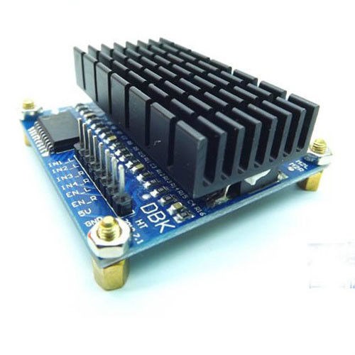
Specs 60A SX7970 Made by: www.sonxun.com.
as you can see in the picture, it has in1,in2,in3,in4, just like the other popular hbridges.
Now, i don't know what the en_L and the en_right is for (i will guess encoders which I won't have on my robot for now.
+5V and Ground are self explanatory.
The problem is when I get the unit in, it has all together different labels and instead of having one horizontal row of 8 pins, it has two rows of 4 pins.
The labels are as follows:
R_PWRL_PWR
3 R_EN (assuming this is encoder but not sure.) 4. L_EN (Where should I hook it?, What pin does it line up with?) 5. R_IS (Have NO idea what this means or Where it should hook up.) 6. L_IS (Have NO idea what this means or Where it should hook up.) 7. VCC +5V 8. Ground
How do all of these pins line up with in1,in2,in3, in4 and EN_L EN_R.
Is seems that the other h-bridges that I used I only used 1234 and +5v and ground for the logic control.
It looks like it's time to ask an Engineer. I am in the dark. Please help me on this.
Thanks, Mel

En usually means enable. These will be used for PWM for speed control if it's anything like the L298n.
I'll see if I can grab a datasheet and have a read over it and confirm all pin connections needed.
Saying that, it has PWM inputs anyway so may be different... IS I have seen somewhere, possibly the Dagu controller... I would guess it is a current monitor which can connect to ADC to let you know how much current is being drawn by the motor.
OK so all I can find is one that looks like this...
Different pin names, different board... The above seems to match your description but not your picture. Which do you have? The one you showed is not the one you said it is.
Do you have a datasheet with it?
Do you know if a datasheet that isn't in Chinese exists?
Right! that's what it looks like.
The reason I bought this one because it was $45 as apposed to $300 that I could not afford. This is the controller for my wheelchair. I completely disassembled the Sunshine robot and I am going to rebuild her. Hopefully!
From the limited information I have seen on the board it is for a single motor not two motors. Hence the lack of 2 connections for motors...
B- & B+ are battery in for the motor supply. M- & M+ are the connections to the single motor.
On the other side of the board we have the 4x2 header. This is where even I get confused since it's a single motor output but you have L and R pins.
VCC is likely to be your +5V from your controller GND is your ground
The rest is unclear and with no datasheet it will be a huge amount of guess work.
Please don't take offence but I would be reluctant to tell you what to try in which order based on some of your posts regarding incorrectly connecting things up.
Some H-Bridges (L298n etc) use In1 & In2 to tell the direction to move, to apply a brake or to freewheel. I.E. if both are high on the L298n it applies a brake, if both low it freewheels, if 1 is high and 2 is low it spins in one direction, if 2 is high and 1 is low it spins the other way. Then the ENa and ENb are used for speed control with PWM.
Other H-Bridges use a different method. The Dagu for instance has current and direction. If current is high it says "Ok, let's go" and then checks the high/low of the direction pin for forward or reverse, while the third pin alters the speed based on the PWM.
I'll have a bit of a better look now I know what it is I'm looking for however, if you got this to drive 2 motors I believe you will be disappointed.
A side note: You get what you pay for. If you want to run high current draw motors you will need a sabertooth or similar. I know the cost is high but they will work without a single problem.
Ah ha!.. Perseverance and thou shalt succeed...
Obviously a poor translation.
VCC is +5v from the EZ-B GND is ground Tie L_EN and R_EN together and put to a digital pin. i.e. D17 LPWM to another digital pin. i.e D18 RPWM to another digital pin. i.e. D19
To enable movement first set D17 high. Then for direction... For forwards set D18 high and D19 low For reverse set D18 low and D19 high
Speed control looks like it may be done by using PWM on D18 and D19.
L_IS and R_IS are current monitoring pins. Connect these to ADC ports for current monitoring. Before you do, check the voltage with a multimeter to ensure that it will never go above +5v. According to what I read I = 19.5 x UIS, so current will be 19.5 x the voltage on L_IS or R_IS (as applicable).
Hey Mel...Why not just use the sabertooth 2x25 which will work fine for your wheel chair base.... it only cost $124 and it is the easiest and in my opinion the best controller in the world to use.... Not sure where you were shopping to need a $300 controller.... And no offense, but you always claim you are so poor but yet in the last little while I believe you bought the wheel chair base and a 3d printer... ! As Rich says, if this H_bridge turns out to have only a single motor channel (which is looking to be the case), you won't be able to use it as planned... Don't cheap out anymore, get the Sabertooth...
the wheel chair was a gift to me. It had the top part broken. Remember, I live in an old folks home. I considered the sabertooth, but I was told that I would need a 60A. This one is supposed to go upto 70A. I cannot afford the sabertooth. sorry.
This controller is supposed to be a dual motor controller. When I saw the first picture you see displayed, it had the same type of connections ; ie; as the sabertooth. I figured it was just a chinese copy of the sabertooth. I bought the 3D printer by going to the loan company and hocking my car. I had the fever for that printer and I have enjoyed it.
sorry if this frustrated you. I have got to stop doing that.
Here is the link. I believe the price is now $20+ but, I paid $39.99 link
Thank You Both for your help and advice.