
cosplaying_bunny
Hi all! i've been a bit busy with practicing my pcb design skills, and designed a 7,5A servo PSU.
specs:
7,5A max out
8-18VDC in power in (ideal for a car batery 9-15V recommended)
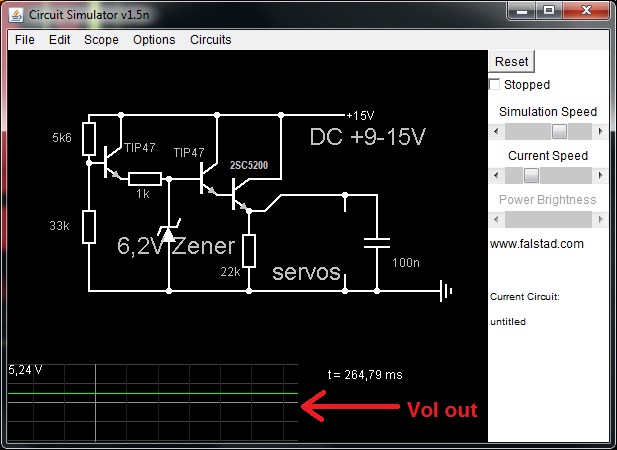
power supply out: 5,05V (@8V in)
power supply out: 5,21V (@12Vin)
power supply out: 5,24V (@15Vin)
9-15V recommended)
power supply out: 5,05V (@8V in)
power supply out: 5,21V (@12Vin)
power supply out: 5,24V (@15Vin)
pcb dimensions: 2 inch x 1 inch
needed parts list:
1x 5k6 resistor
1x 33k resistor
1x 22k resistor
1x 1k resistor
1x 100nf cap
2x tip47 transistors (or other NPN transistors)
1x 2sc5200 transistor (or any other NPN one with a high current capability~)
1x 6,2V zener diode
a way to make your pcb (be it etched, on a expirimental pcb or another way)
a heatsink (standard 60w cpu heatsink should work if it has a solid aluminium base large enough to fit all 3 transistors)
and of course your servos!
optional parts: screw terminals for on your pcb.
approx costs of the parts (excl pcb and servos): around $10
i hope this is usefull for the community to make powerfull power supplies here is the schematic:
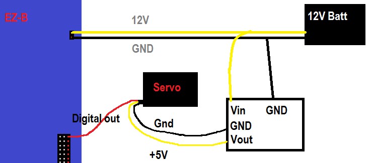
and how to wire it up:
the pcb with it's components:
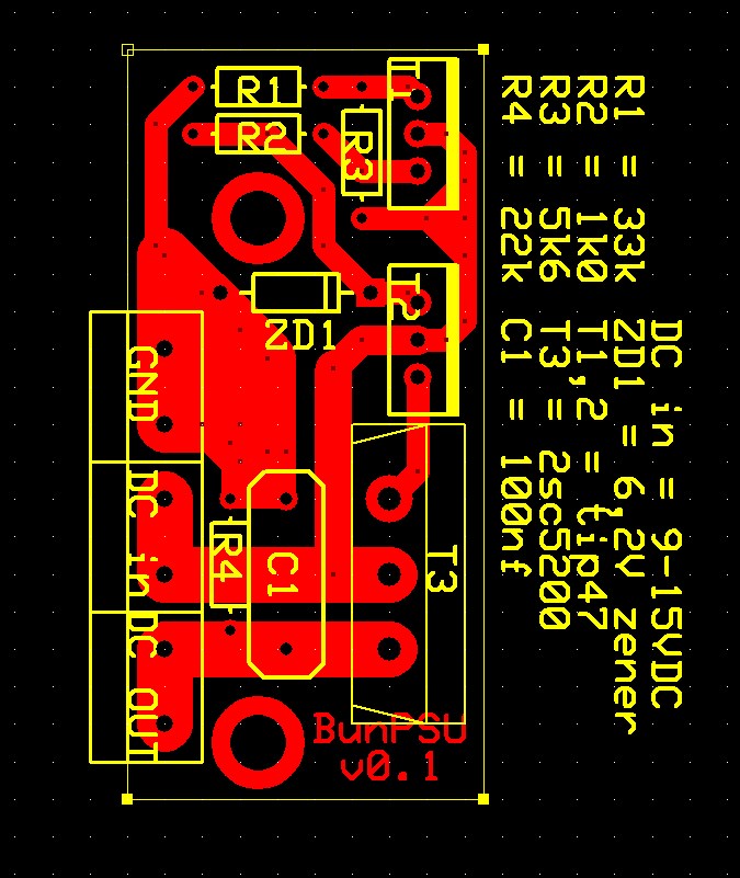
and finally, the pcb itself (non-mirrored!) on a non-scale:

important!: i am not responsible for design errors or anything, i just want others to know how they need to make this sort of stuff!

I don't know if you started already started but I was going to make a suggestion. Servos put out a lot more power when the appropriate voltage is supplied. Standard RC servos take 6 volts in and operate cooler when voltage is correct. Many High torque servos ( if not most) accept 7 volts DC. Undervolting servos reduces power significantly. Just food for thought when you do your next one so 6 volts standard and 7 for high power/ high torque servos.
i didn't know that honestly~ and the answer is simple: to get an higher output voltage, you could simply replace the zener diode with one with a higher voltage (i used a 6,2V one in the schematic, you could use a 6,8v one for around 0.4V more power)
What advantages would this have over an LDO voltage regulator circuit?
at least that i had something to do which i like, which is pcb designing x)
maybe for other users: a soldering practice, something to be proud of because they made it themselfs?
and i honestly don't know what a LDO is.. :o
edit, i searched it up, and found out that the 78xx and 79xx are LDO's
which i have a 10A schematic laying around of it.
An ldo regulator still needs a PCB, perhaps your next project
LDO is a low drop out regulator, basically it has less losses and produces less heat etc. One of them, a couple of capacitors and some resistors and you're done. Google it and you'll see schematics I'm sure.
updated my post above blush and made a pcb for it. 7,5A max, 6V out based on a 7806 LDO regulator and a 2sc5200 transistor same pcb dimensions, 1 inch x 2 inch~
hi all, there's a new version of my psu, for those interested. this time it's a 20A one (maybe even more) it is based on a lm7805 (or lm7806 for 6V output) and 2 TIP36C transistors. the input voltage is: 9-14V, and the output is 5V (if you use a lm7805) with 20A note: if you want to use this psu in your robot, be sure your battery or power supply can handle at least ~30A of continous load (when fully used)
there are a few reasons why i choose this design: you can easily upgrade it from 5V to 6V out, simply by switching the volt regulator, you can easile add more transistors for greater power also: it is cheaper to upgrade it, because 1084 ic's aren't that cheap, and one TIP36C can handle more than 10A out continous (equals 2 1084ic's)
there are also a few things why you shouldn't use this: when you need a compact power supply (it is a bit large) or when you have a low input volt of lower than 9V with less than 30A out continous.
note: this is really only usefull for advanced robots with ALOT of servos (say more than 30) and too high input voltage or for robots which have current-consuming servos (like digital servos)
use at your own risk and USE FUSES in case of short circuit or what ever, oh and also use >10mm2 for the wiring because of the current draw.
pcb design in the zip