
Circuits.io is an online, browser based schematic drawings, PCB design and breadboard simulation package by AutoDesk. It can be very useful for testing out circuits before you even get around to physically building them and even has a built in Arduino script simulator (which can be useful for testing out how switching of ports or ADC values can effect circuits).
The software is pretty simple to use however I decided to write some tutorials on how to use each of the...
Step 1
Circuits.io is an online, browser based schematic drawings, PCB design and breadboard simulation package by AutoDesk. It can be very useful for testing out circuits before you even get around to physically building them and even has a built in Arduino script simulator (which can be useful for testing out how switching of ports or ADC values can effect circuits).
The software is pretty simple to use however I decided to write some tutorials on how to use each of the different parts of this software and have a step by step guide on building circuits.
Below are (or will be when I finish them all) tutorials for each part. This will be updated to eventually cover all parts however, for the time being I only have the schematic section completed (bear with me on the other two).
Circuits.io Schematic Tutorial
The first thing you need to do is make sure you have an account, so point your web browser to https://123d.circuits.io/circuits
Then click on either Sign Up or Sign In depending if you have an account or not.

If you don't have an account simply sign up for one. You can sign in using Facebook too to save you filling in any forms.
Once you have signed in you should be greeted with the main screen where you can see their tutorials, your previous projects or create a new one. We will want to create a new schematic so go ahead and click on the New Schematic button.

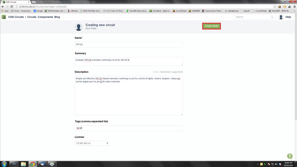
Now you need to fill in some details about the project such as the title, a summary, a description, some tags and finally the type of licence you grant.
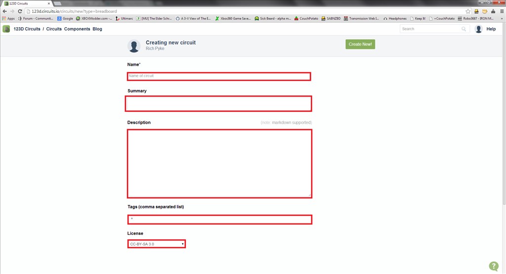
Go ahead and fill it all in.
You should now be greeted with a nice blank canvas to play with and a pallet of tools and symbols to the right of the screen.
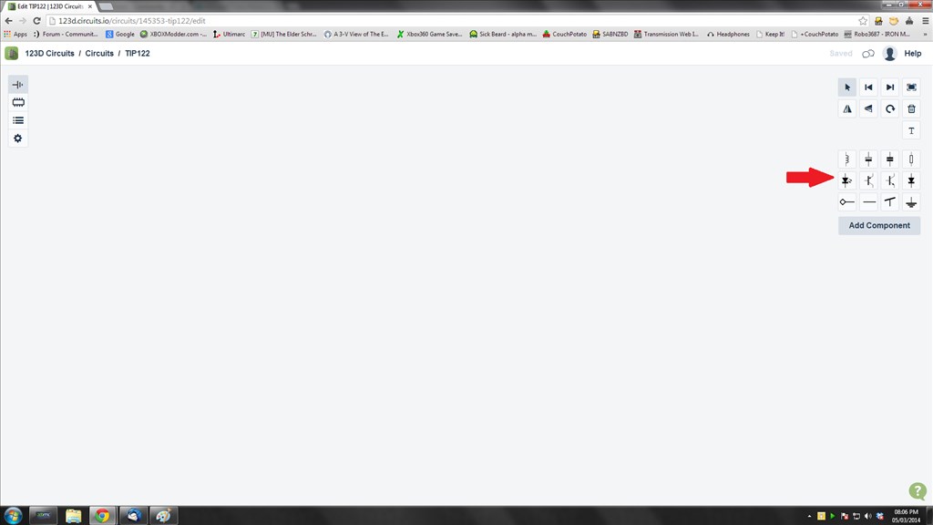
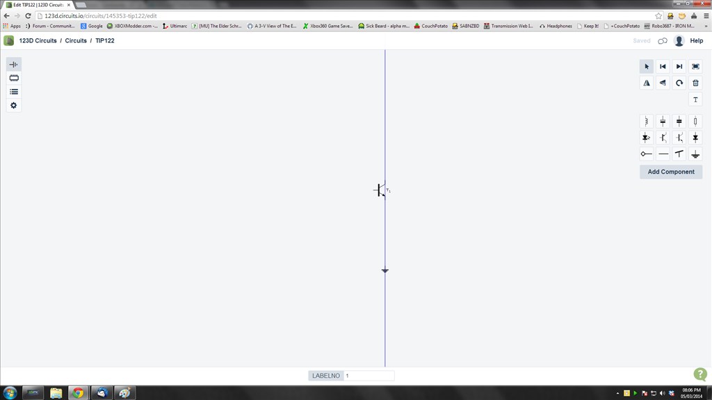
So, let's make a simple schematic for the trusty old TIP122 transistor switching circuit. The first thing we need is an NPN transistor so we click on the symbol for an NPN transistor
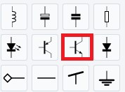
And we place it down on the canvas with a left click

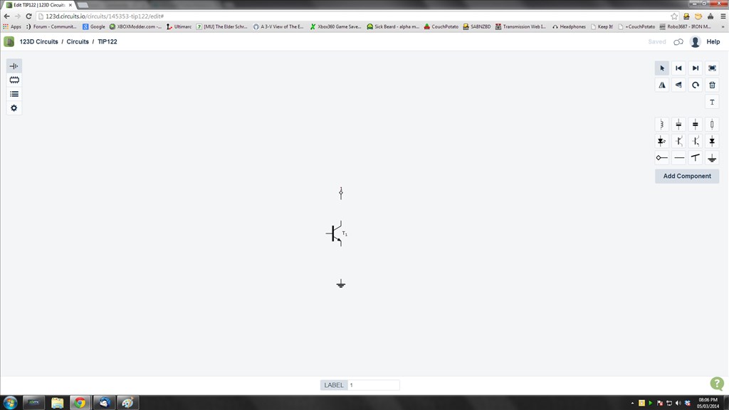
Next we want our ground so we select the ground and place it on the canvas too, notice at this point we get a blue line to aid in aligning with the other parts already on the schematic.
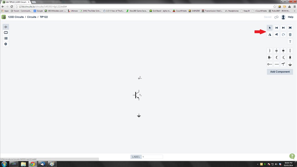
Next we add a node, which will be going to the item the transistor is switching, be it an LED, lamp, buzzer, motor or whatever, so select the node and place it down. The node will be at the wrong rotation so once it's placed down click on it to highlight it and select the rotate button from the pallet of tools.
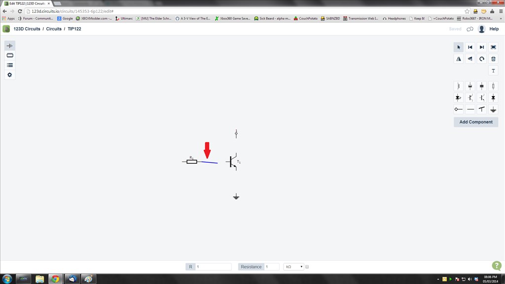
Next we need to add a resistor, so select the resistor and place it down
And now it's time to join it all up with circuit lines. To add these simply click on the end points of any of the components, a blue line will now be joined to the component and your pointer, then click where it needs to go to and the circuit line is added.
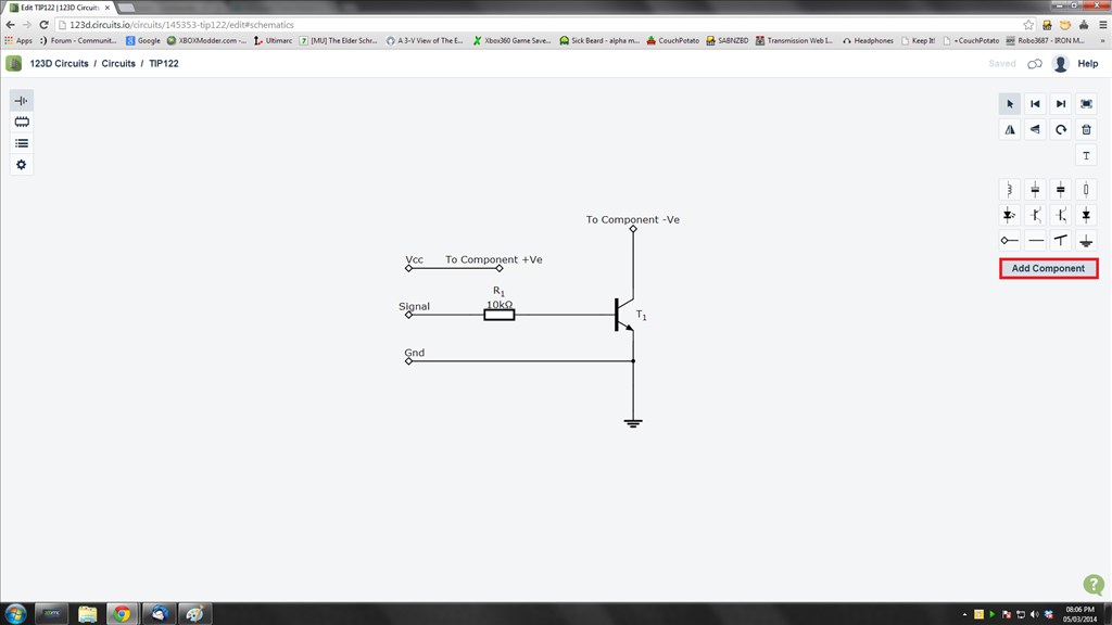
Add in the other components, nodes and circuit lines to complete the circuit. Then add in the labels for the nodes. To add the labels, or to change the values and part numbers of the components click on them, at the bottom of the screen the information will pop up, simply click in the box and adjust the text to suit.
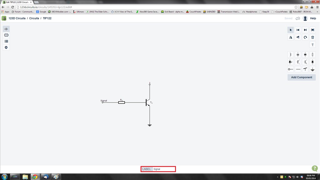
And we have our circuit.
If the component symbol you need isn't in the pallet, for instance a relay, the option to add a component is also there, just click on it
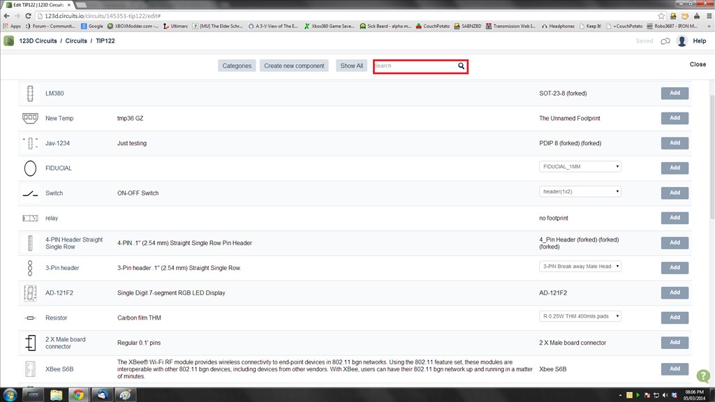
Up pops a dialogue with a whole range of new components. Use the search box to narrow down the search. Click on Add to add it to the pallet.
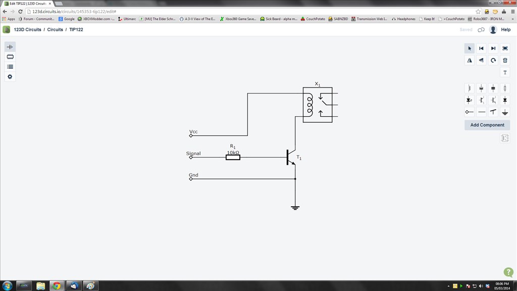
Then add it to the circuit like we did with the other components, click on the icon in the pallet and place it on the canvas. Connect it up with circuit lines and viola.
The circuit will automatically save throughout drawing it so next time you go to the main screen the circuit will be under your circuits.
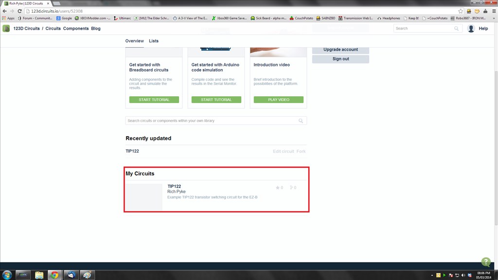
And that's it, you have just drawn a circuit schematic. You can print this, share this or edit this all from the main menu. Just click on the circuit picture or title and it will load up all of the information you need.
PCB Tutorial Coming soon
Breadboard Tutorial Coming soon
