Asked — Edited

Xl Rover Prototyping Community Feedback

ANT is doing a great job getting the first proto of the XLR6 ready to send to me to start working on so for the sake of planning I would like to listen to the communities ideas for a rover kit and rover base. The EZ Robot kit is a great place to start so we aren't trying to replace Roli. This is for the next level kit , more ridiculous add ons can be made later. I will share some of what we have in mind so far. As always all our projects are being developed for use with ez robot Ezb v4 but you can still use a v3 in them.

Rover kit , that's a top and bottom to make the whole Xl rover

  • misc parts like wheels

Rover base only, that's the bottom half of the Rover frame with wheels and a flat tray on top all molded from 80A shore urethane plastic


ARC Pro

Upgrade to ARC Pro

ARC Pro is your passport to a world of endless possibilities in robot programming, waiting for you to explore.

#1  

User-inserted image

The Zero Degree Rover

User-inserted image

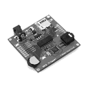
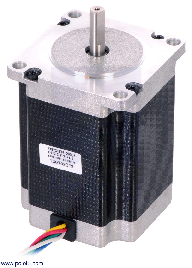
want to go fast? Driving a skid steer base is difficult but you can switch modes. Lock the rear in place and turn only the front servos. ZOOOM...! This versatility is not found in any other rover base kit. 6Wd and individual motors for each wheel give power in a small package without noisy plastic gears. Gear reduction comes with its own problems. The motor pods are for a 40mm Nema 17 stepper. Alternate mounts can be swapped for 58mm Nema 23 steppers or even continuous standard servos. This is the staple of modular versatility!

#2  

This is Cool! How would you mount the motors? Hinged? spring loaded? EDIT: One Idea I got was to do a 4WH drive version. this is my concept of this in 4 wheel.

User-inserted image

If you use it, go ahead! But give a shout out to me.

#3  

I really dig the two driving modes via locking the other ones in place. nice work so far josh.

#4  

Just some little tests , i poured out a few ounces of the plastic in to a square so i could test things like deflection under pressure. This is 6000 psi tensile strength urethane. The thickness is a hair over 1/4 thick. The pattern in the middle was from where I moved the mold right after pouring. This stuff hardens in 90 seconds so it literally changed from dark brown to tan in seconds. It's good to let it sit for a few minutes to cool. The temperature jumps to around 250 degrees when it changes color so i let the stuff cool a few minutes. User-inserted image

Obviously parts inside a mold come out perfect. What I have quickly learned is its not required to have super thick walls with this material.

#5  

User-inserted image

Here is the test square popped out of that mold. The masking tape is stuck to the back which is fine because I am just testing strength of the material. At this point trying to bend it with hands and legs didn't work. This is super tough material!

#6  

@jstarne1-XLRobots.com Josh, where do you get your urethane at, is it available in stores or do you buy it somewhere online, just wondering :-} Steve

#7  

You can get a similar product from hobby lobby two part liquid plastic casting resin. 28 ounces is 25 to 30 dollars. Obviously if you buy larger amounts the cost per ounce drops. If you decided to do something custom get yourself a accurate scale. It's much easier to pour into a mixing container by weight than wasting measuring cups.

#8  

@antron , thanks by the way. If the base of this rover didn't have the plus features like this , it wouldn't be any better than the ones already out there.

#9  

Ok tiny updates for this project design. I ordered and chose a entry level high torque Nema 23 motor for testing. It draws 2 amps per coil with 2 coils. So that's 4 amp total. Voltage range from 3.6v to 45 volts. Case size is standard 57mm x 57mm for NEMA 23 and 76mm long for the largest case. Take in mind there are 125 oz -250 oz in versions that are only 58mm long but they draw more current to get that torque from a smaller coil. I will write a expert of motor choices and why I'm going with steppers as a standard. User-inserted image

User-inserted image

User-inserted image

User-inserted image

Now that I have the motors modeled I can use these as reference to design the motor pods and the chassis. Since the rover is 6 wheel drive I am using 6 individual high torque motors. Gearing us available for the Nema 23 motors but with these torque ratings it won't be needed.

#10  

This is what they are modeled after and I have them in the mail to arrive in a couple days. These steppers are from pololu but thanks to industrial standards you can buy these motors just about anywhere and I have seen them as low as 20 dollars but you have to wait on China shipping. User-inserted image

#11  

Good morning EZ Robot Community!

Today I wanted to post a tiny bit about steppers, how they are controlled and you shouldn't be afraid to use them. One of my biggest concern about entry level and midrange robotics is the heavy reliance on plastic gearboxes and in some cases brass gear boxes. They are typically very loud , and unreliable once you start adding batteries and equipment to your robot. Stepper motors however are brushless high torque motors that don't need a gearbox. They have torque ratings in the thousands of ounce inches. The also come in sizes as small as 40mm X 40mm Nema 17 for a small robot and 57mm x 76 Nema 23 for larger robots. They operate on pulses from your EZB but not pwm. The speed the stepper moves will depending out how often a pulse is sent to the motor and it will move 1.8 degrees for every pulse applied either forward or reverse.

So why a stepper?

  • High torque motors :starting at 125 ounce in on a Nema 23 , we are testing with a 190 ounce inch @3.6 volts. Don't be fooled by the ratings though. It is common for steppers to be ran ten times higher than that and the torque curve rises with voltage. For testing purposes I will use a Texas Instruments 2.5a stepper controller that can handle up to 45 volts. We are shooting for 12 volts which is still 4 times the original torque rating.

  • industrial standard ratings and casings make buying a motor to fit easier and replacements when needed.

  • steppers are rebuildable. The coil can be rewound if ever damaged by over heating. Try doing that with a 100 dollar wheelchair motor! (Possible but not made to disassemble)

-Accuracy : by default each full step is 1.8 degrees but in a sudden need for more accuracy a simple (digital pin on) can trigger micro stepping up to 1/32 of a step. ( that is about 1/16th a degree).

-Reliable control: because of the previous mentioned control on rotation if you wanted for example to tell your robot to move forward 1 foot, you could do so will great accuracy. This would not change with the grade of the surface. Let's say you wanted you robot to turn left or right, 15 , 30, 45, or even 90 degrees then it could do so with accuracy as long as the detent torque limit is not exceeded. (Aka as long as all the motors do not stall from getting stuck the turns are accurate)

Here is lots of technical info but what is important to know is with a simple script, time designation a microcontroller ( like ezb) can control this with the aid of a stepper driver.

http://en.m.wikipedia.org/wiki/Stepper_motor

The l298n is a basic stepper controller but it takes one l298n to drive a single stepper because they have two seperate coils inside. L298n does not have micro stepping capabilities, feedback for stalling or limitation of the current. A BVR8825 Texas Instruments driver is a cheap and effective choice.

#12  

Here is a forum explaining the use of l298n and other controllers for steppers. For those who want a more sophisticated controller I will make one available when the base is released.

https://forum.allaboutcircuits.com/showthread.php?t=37626

#13  

One of the goals of this design is to make a complete rover as well as just a rover base that can enter a doorway , pass through and if it needs to turn around it can do a zero radius turn and exit the doorway smoothly. The wheels turning helps but the robot cannot be too long or wide either. The type doors are 30 inches but because of the edge of the door and hinge that is realistically a 28 inch opening. This is the target space we are working through. User-inserted image

#14  

Thanks Josh for the stepper overview! My question is why aren't they used more often? I would presume because they require more support boards ie stepper controller and digital output pins which all add extra cost.

#15  

They aren't used as often because they are more complex. Instead of applying power through two wires and you go, you need a microcontroller driver to send pulses to them. They use to be really high priced but thanks to DIY community with 3d printing and cnc machine projects the market for competitive stepper motor prices has emerged. Mostly I believe it is the intimidation to the customer that he or she won't figure out what to do with them. Thanks to newer and easier to use drivers and software for ezb this kind of quality in a home made robot is easier to obtain.

#16  

wanna see how much more accurate steppers are for a drive system? this is 1/2 step accuracy , but motor controllers im looking at are 1/32 microstep accuracy. At 1/2 step accuracy this little dude runs for 10 minutes in a predefined square before a wheel catches a edge of the table.

https://www.youtube.com/watch?v=831qjVX6YLA

#17  

I'am impressed! The steppers seem to have a lot going for them and your exposure will certainly convince more robot builders to try "them out" Thanks again :)

#18  

@IRobot - Thanks man! here is a little test video i stumbled on show how a stepper can run on various voltages, with higher voltage the operating torque rises and without any load at all the motor will spin very fast. Take in mind he is not using a controller on this motor just a makeshift circuit that is generating a great deal of electronic buzz that is not typical with stepper drivers / h bridges. It shows the same NEMA 17 55 oz in runnin 6 volt, 12 volt and 18 volts. They can go much higher , up to 45 volts for small electronic drivers like what we will use. The motors "rating is only 3.0 volt so you see the direct effect voltage has.

https://www.youtube.com/watch?v=i-8LaQHZzF8

#19  

Lots of awesome info Josh. Thanks for all of the info and sharing your research with us.

#20  

@ Antron007 , Thanks Antron. Educated purchases are the best purchases! ;)

General update - I am mocking up a wood body over the next day or two with the general specifics of my sketches so i can get some more measurements to create the motor mounts on the end that swivel. Once i have test body i will check some measurements for the mounts and if i need to make size changes to optimize the body shape. Take in mind this is the business end of the " solid frame" indoor rover and the top half will be more cosmetically pleasing. The top half of the shell will cover the bottom.

#21  

User-inserted image

User-inserted image

User-inserted image User-inserted image

at this point the rover is a electric " motor in wheel" design. Because the front and rear wheels have their own motors this can be a quad "smartcar" as well and still retain the maneuverability but drop weight capacity without the center supporting "axle". These are just rough sketches and I will update with a live mockup to.

#22  

Here I'm working on the mockup similar to the initial sketches.

original basic function sketch.. User-inserted image

Here comes a wood model to get real world perspective and also give us a better grasp on measurements for the 3d design aspects.

User-inserted image

User-inserted image

User-inserted image

I just glued the joints together and it takes a few hours for the glue to dry completely so i am done for tonight. You can imagine it sort of coming together.

#23  

Overlay doodling , yea it looks like crayons I know lol. User-inserted image

#24  

jstarne1-XLRobots.com, Your wood model looks good! Steve

#25  

Thanks Steve ! I appreciate the positive feedback and support. This is made for the robotics community by the robotics community.

#26  

Playing with some size options here , the one to the right is a possible "mini" rover that would be more appropriate for 40mm Nema 17 motor sets. User-inserted image

Canada
#27  

Great job so far! We have learned alot about improving our designs after we actually printed and assembled a mockup. I am excited to see the next steps with your rover :)

#28  

@Josh ...... @Jason has a good idea with building a mock up! Cut out some high density Styrofoam or wood and get a good "visual" of the overall appearance etc!

#29  

One disadvantage of 3d modeling is you can spend hours drawing them realize things don't physically fit the way you want so to get the initial base / permanent measurements I'm building a mock up of the basics then once I have a physically compatible model I can input them into autodesk and it makes the rest of the design so much easier :)

Right now I'm making a mold of the NEMA 23 Stepper so i will have blanks for the whole physical mockup. I also have Nema 17 on the way for the mini rover mockup as well. User-inserted image

all holes on a part that we don't want rubber to enter must be sealed with clay. I filled 12 screw holes and the holes on each end of the shaft as well. Then a mold box is custom build around the part so that you don't waste material. The manufacturer says the parts typically only need 1/4 around the part but I gave a little more space because it's a thick cavity , about 2.2 inches thick and 4 inches tall.

next step , pour some rubber

User-inserted image

I'm making this look very easy by leaving out some details. When making a mold you must first put the rubber in a vacuum to degass the liquid and then apply pressure while the mold cures forcing the rubber agianst the part. This picks up every detail of the part. In this case I was not concerned about detail for a pre design mockup. My professional vacuum setup arrives today. A mold takes 16 to 18 hours to cure under ideal conditions. I will demoed this evening and assuming me neglecting to degass and pressurize the mold didn't cause any issue I will cast a few duplicates. When i do the casting I will record it just to show how fast this process can be with the correct equipment.

#30  

Ok so i casted a dummy copy of nema 23 motor with 8.4 ounces of liquid plastic. The colors are from dye , i did a red one too playing around. User-inserted image

User-inserted image

User-inserted image

User-inserted image

#31  

Here we are building the mold box for the Nema 17 40mm motor which is much smaller than the nema 23 big brother. So once this cures tommorow I will cast 6 nema 17 duplicates as well for the Zero Rover mini. User-inserted image

User-inserted image

#32  

Here's 3 motor blanks lined up agianst the frame... User-inserted image

#33  

Ok so i have all 6 nema 23 motors and all 6 smaller nema 17 motor blanks casted and now I can build around those. I will post some more napkin sketches soon.

#34  

Ok here's the 6 nema duplicates... User-inserted image

User-inserted image

User-inserted image User-inserted image

Mini Zero Rover

#35  

Here's the nema 23 blanks next to the regular size Zero Rover User-inserted image

User-inserted image

User-inserted image

#36  

Interesting! I am following this project.

:):):):) J

#37  

WOW Josh! when you do a model , you go all out ! Awesome! Is the rubber your using an RTV type? :)

#38  

Hi yes it is a RTV silicon rubber , 15 shore rating which means it is somewhat flexible.

Thanks for watching guys. The goal is for this platform to be well thought out and versatile. Building those options if thst we wish every other chassis had. I have tried over a dozen wheel types and that's one of the next things to be designed. Once there is a wheel design then the motor mounts will be designed to adjust ride height and have solid stiff suspension or off road with 100mm oil filled shocks. Two shocks for each wheel is possible for a heavy robot yet able to tackle terrain as well as the wild thumper. A advantage over thumper is the surface area will be 2.5 times greater on top for those who want to make their own top of the chassis.

#39  

Here are some napkin sketches for suspension and possible layout for the top of the rover. As I have previously mentioned the Zero Rover will be availavailable with various interchangeable add ons. Also I will sell it with a naked top for the diy people who just want a excellent start for a robot base. User-inserted image

User-inserted image

The first is solid suspension with no shocks. This is for indoor use and mild outdoor ventures. This does not picture the Zero radius turn spindles.

User-inserted image

User-inserted image

This is the naked base with fully adjustable suspension. Using oil filled 100mm aluminum shock and springs , the right height and stiffness may be adjusted. Second is the adjustable "hard frame stop" . This adjusts the highest point the wheels can travel. In situations where heavy weight exceeds the shocks capacity the suspension rests on these stops. The shocks can be adjusted to intentionally rest the suspension on the frame but when uneven gaps in flooring are crossed the wheels reach down to maintain traction.

#40  

User-inserted image

Here is the contemporary "smooth" rover top front view with comparison of hard and soft suspensions

#41  

I love the concept of a military or stealth theme because of the rugged feel. Agian just napkin sketches for the tops. A center sphere is common in both designs and a feature I am sold on that I simply only see in professional robots and military / industrial equipment. In both cases a ultrasonic rangefinder and camera is in the sphere. I want it fairly large so addition sensors , stereoscopic cameras or other sensors can be utilized in the same enclosed pan / tilt assembly. User-inserted image

#42  

Ok so I really needed to get suspension components that are standardized enough to be purchased anywhere in the world but also available at a low cost. Some aspects of chassis I won't make public but others are important right?:) i will measure these units and then model them as a 3d stl. The rest of the suspension length and shape depends on these numbers. Here are pics of the shocks. They are in fact oil filled and use a coil over progressive spring. At this point there are various angle choices and options to have either one or two shocks per wheel.

User-inserted image

User-inserted image

User-inserted image User-inserted image

#43  

@Josh I really like those mini shocks and they are oil filled also, they look like a good quality and sturdy shock. Very nice indeed :-}

#44  

@josh - Are those offroad R/C shocks? What brand is that? HPI usually has purple anodized aluminum parts.

South Africa
#45  

Where did you do all the 3d designs on

#46  

Hey, the shocks are unbranded and direct from china. They do resemble hpi so maybe they are the same , i found pictures where they literally look identical. I wanted to use a format that gave the end user easy upgrade options from a local hobby shop or online provider. They are compatible with alternate springs and heavier weight oils as well. The plan will allow for swapping of shorter 80mm shocks as well. That was one of the limiting disadvantages I saw in completely proprietary spring suspension like in dagu wild thumpers

#47  

@Josh More than likely they are the same shock as the hpi ones. Lately I have been ordering parts and pieces off of Ebay from China, I cannot beat the prices, none of the stores around here even come close on the price and most of the time the shipping is very cheap or nothing at all, now I don't understand that at all.

#48  

Muhammad , i started using 123d design which is more basic but user friendly and produces stl objects easily. It's a good idea to download and start learning blender and Netfabb as well. You can start a object in one program then migrate it to another for creating complex curves objects you can only do with mesh. Take in mind I'm still new and I recently downloaded 3ds max but I'm still very new to it.

#49  

I think I know which shocks you are using. I believe I found online. I really like the idea of this platform and have been watching the thread.

I'm probably not as much of a community member as I feel like I am because I mostly just lurk but how far along are you on suspension development and are you open to suggestions on it? I wouldn't call myself a suspension expert but I have raced both onroad and offroad R/C and have some experience working with this kind of small scale suspension.

#50  

Sure if you have suggestions I have open ears.

#51  

Ok. Here goes....and only because the thread title says "community feedback"

From looking at your sketches:

  1. You probably don't want to do the suspension underneath the main body like that if is supposed to be an "off road" version. The suspension arms being underneath like that will reduce ground clearance and will have the potential to get hung up on rocks, sticks, and the like. The bottom should be as flat and smooth as possible to get over those kinds of obstacles without getting hung up on them.

  2. You show the shocks being mounted in a straight up and down configuration. Most R/C every vehicle I have used has the lower part of the shock outside of the upper part of the shock. Having the shock straight up and down creates side loads on the shock as the suspension arm moves up and down through it's arc.With the shock at and angle it works much more efficiently. Also, with the shocks at an angle, you have the added benefit of the shocks being able to help stabilize the vehicle from side to side. A straight up and down shock configuration is not very stable in that regard. The picture below shows what I am talking about.

User-inserted image

Anyways....thats just my 2 cents.

#52  

Hello everyone , summertime is great for distracting you from the cool things that usually happen indoors. Thankyou for the feedback. I believe I will print a bracket that allows for 3 or 4 possible mounting points for the top of the shocks. I just rebuilt a new pc and now I must order replacement parts for the maker bots because they developed an epic clog all on the same day. Given the interest in ez robot projects I decided to go back to college so I have had a busy month running countless errands. Now that I have a 3d machine back agian I can get going on 3rd design and printing all the misc parts for zero rover. My last update of any significance was the 100mm shocks that came in for my suspension. After Some Thought I Like The Smaller NEMA motors as a standard then larger ones as a heavy duty option that I imagine will not be as popular.

#53  

Alright , slight update. The " standard" sized version of zero rover I am working on will use Nema 17 motors. I ordered 6 of them as well as 6 controllers to run them. Also I realize at time we don't need the nicest setup to start out so I'm going to model alternate motor mounts that use a standard servo instead. That way for the sake of budget someone could afford the base if the only other alternative was a Dagu Rover 5 ( not EZR Roli)