Asked
— Edited
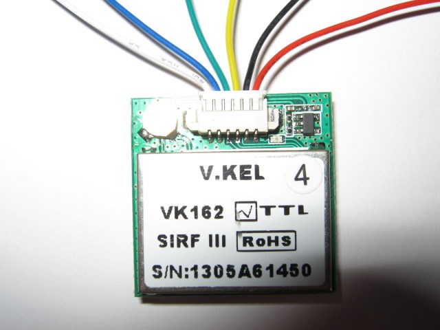
Vk-162 Gps Module
The actual pinout assignments for this device are shown in the next to last image posted.
 Sharp IR Collision
— Stops movement panels when a Sharp IR sensor on EZB ADC detects objects within a set range; displays ADC voltage, VU meter and 0-255 distance value.
Try it →
Sharp IR Collision
— Stops movement panels when a Sharp IR sensor on EZB ADC detects objects within a set range; displays ADC voltage, VU meter and 0-255 distance value.
Try it →

Text removed since a wiring solution has been found and documented in this thread.
It is recommended by DJ in the thread below
6PIN :GND,RX,TX,VCC, (BOOT.P) for upgrading or other functions
https://synthiam.com/Community/Questions/3290
GPS help
The 6 leads coming out of the GPS do not agree with the 6PIN designations.
In the first picture P, and GND are not on each end of the 6 pins but are together on one end as (RED, and BLACK). When those leads are connected to power then the GPS LED turns on but nothing else happens when the Yellow and Green leads are connected to the TTL/COMM USB device @ 9600 N, 8, & 1. Which brings up the original question, what pins of the actual GPS are connected to the six colored wires on the plug provided with the GPS unit?
I'm just guessing with this layout.
feel free to edit this pic to show how you connected it.
No idea what pin is what so DON'T FOLLOW THIS DIAGRAM.
EDIT: As suggested, "Don't use that wiring diagram"
Use the pinout described below....
Here is a variation of lead designation that will work. Just use the Vcc, Gnd, Tx, and Rx leads.
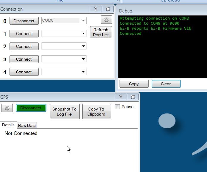
Success ! If the GPS module is wired like the lead designations above then you will have a working GPS. Just use a COMM port optioned for 9600 baud, N, 8, and 1. All you need to wire are 4 leads (Gnd, Vcc, Tx, Rx) Then you will get a good feeling when you either connect through your EZ-B or a GPS PC program.