Doombot
USA
Asked
— Edited
Triggering 12V Relays From Digital Ports
Hey guys, what's the best and safest way to trigger 12V Relays from the Digital pins? Thanks.
I tried a Tip120 Circuit with a 1K resistor, didnt work, then with a 2.2K resistor, didn't work. I have an LED hooked up to the digital pin so I know it works, the LED lights up.

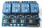
For EZB 4 i use one of these.
4 Channel 12V Relay Module Board Optocoupler LM2576 Power Supply Arduino
With one of these. Logic Level Converter 3.3V to 5V TTL Level Converter Logic Bidirectional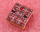
Both available on EBAY for cheap...Datasheets available online.I use these and use 5 volt power from a dc to dc regulator.
I am pretty sure you need to convert the 3.3 v EZB 4 digital output to 5v in order for it to work correctly.I could be wrong but i tried the 5v relay board you have and it would not toggle relay..
I was using three of the relays pictured above with an EZB(4) without issue. I have run into issues when using the UART to communicate with the later model Roombas though. Had better results using a logic level converter with TTL signals.
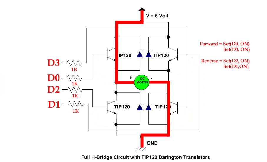
Thanks guys I was gonna use these relays to trigger my 12vdc window motors (they pull about 10 amps each) but I'm experimenting around with tip120's and I just made an Hbridge using four tip120s. I'm gonna test it tomorrow. I'm giving credit to rb550f since he responded first. Thanks!
Here's what I used:
I changed the shorted out B1 and B2 to four separate digital pins. Here's what I did:
What do you guys think? Am I gonna be able to apply PWM to this or no dice?
P.S. I'm using this setup for the shoulder motors, not for the drivetrain. I'm using a 300A electronic speed controller for that.
:D
I have used one of these for up to 30 amps. For Arduino VNH2SP30 Stepper Motor Driver Module 30A Moto Shield Replace L298N
It cost less than $14.00 same one that Sparkfun sells for $70.00And yes you should be able to use pwm for control of your circuit.
Doombot, On your cct, never enable D0 D2 or D1 D3 at the same time else you will see smoke as these will be short circuits. A lot of homebrew H bridges use an (logic) invertor on these lines so this can never happen.
Likewise a 1 1 (on B1 and B2) of the first cct will also cause much smoke, its easy to accidentally do this with a simple coding error, the invertor method averts this.
Tony