
Asked
— Edited
Status LED Fail
Hey!
Yesterday i was driving around with my robot powered by EZ-B when it got stuck in forward (not the software but the ez-b itself) and i couldn't stop it, i rebooted and it got stuck in turning.
Now i powered it up but the Bluetooth module light won't come on, then it finally came on and everything works as normal but the status led doesn't work. not even when i try to turn it on in ARC blush

That's because if it sends a signal and nothing is connected, it doesn't get anything back so it maxes out (i think 64 inches is the maximum distance you can measure in ARC)
That doesn't make sense though. I connected that PING sensor the same way DJ did. I even used the default pins on the EZB. Besides, the first time I connected the sensor it worked fine, since then nothing. This is so confusing blush
Same here. Actually status light was not working from day 1 when I recieved the EZB, but everything else still works
artdude... I have the same problem as you with my newest board. The blue led has never come on but it still seems to work...
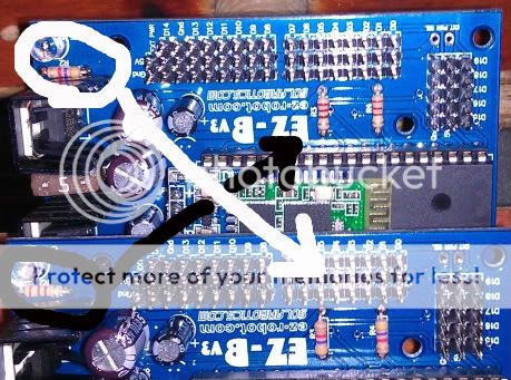
After comparing both my boards i have a clue but one of you smarter folks will need to tell me for sure. I have different resistor values in different locations? The resistor value on board 1 in the r2 spot (next to the led) is the same as r3 and r4 on board 2 and visa verse.
The board that works is the one shown on top in the pic. could this be the problem with your board too?
and could a mix up like this be the cause of other problems folks are having?
Ron
This is interesting on my board
R2 is a 4k7 (or 4700 ohm) resistor yellow purple red R3 and R4 are 220 ohm red red brown so the same as board 1 above and this board works
R2 is just a current limiter for the LED looks like so if it had only 220 it would have blown. I can't tell what the other resistors are for but this is a considerable difference in values so thats not going to help but may not be important?
Looks like an assembly issue. I would consider changing R2, R3, R4 and LED (get this round the right way as well) and see what happens
However looking carefully at the V3 board pics on this site I can see some early V3 boards could be different. As my board has R1 missing for instance possibly the early V3 components have found their way onto later boards with a different layout but I'm just guessing. Someone needs to try out the resistor swap I guess?
Good spot brw_racing
My LED works, but I cant hold a connection. Anyways, on my board I have the same combinations as Winstn60
R2 is a 4k7 (or 4700 ohm) resistor yellow purple red. R3 and R4 are 220 ohm red red brown.
I suppose you all have a Diode jumping from D1 to R1 on the left side of the board (side with power adapter). This looks strange to me, any answers?
Well, here are some answers to your questions:
First of all, for TXTCLASS: sorry your connection problems probably not resistor, LED, or D1 related. It's gotta be either your Bluetooth module on board or the Bluetooth dongle you are using (maybe it's even a worn out USB port).
For the rest: You have stumbled onto the minor issues that came up when building the EZ-B, the weird D1 mounting was as a result of a PCB error, if you look close you can see that C1 was shifted and it wasn't picked up until the PCBs were out of production. Sometimes small flaws like these are unavoidable, anyway the mistake was patched with the re-orientation of D1 and the imposing pads of shifted C1 were corrected and tested on every board.
Another small mistake in manufacturing was the ol' switcheroo of the 4.7K resistors with 220 ohms. The designed values are R3 & R4 = 4.7K and R2 = 220. While the boards with the opposite will work just fine the only difference would be that the LED would be much dimmer with R2 = 4.7K ohm due to the high resistance. The resistor being 220 ohms was designed around the standard current limitations of 5mm LEDs which is ~20mA. So here's the calculation: A 5V signal (high) from the EZ-B through the 220ohm resistor (5V/220ohm) = 22.7mA and this is quite a reasonable value for the LED. Be aware that in previous versions of the EZ-B the LED was tied to the PIC chip directly without a current limiting resistor, this would have run the LED constantly at 25mA and no problems were seen that I'm aware of.
I can also add that I've been running my EZ-B board for months with the 220 ohm resistor on the LED. I would guess that issue here would be a cold solder joint on the LED or resistor pins on the boards that don't light up the LED. I would suggest to try resoldering the LED pins, R2 pins and the LED pin on the PIC chip (on the underside of the board) to see if that'll remedy the situation.
So for R3 & R4, they are I2C pull-up resistors for the I2C breakout header, 220 or 4.7K ohms doesn't seem to matter, my I2C BlinkM module works flawlessly with either. 4.7Kohms is just a standard value across the industry so that's why that value was chosen.
Well there's the long winded answer for you guys so you'll never have to wonder . In short try resoldering a few pins.
I replaced the resistors like they are on yours and my first board. board still works fine.
I pulled the led and replaced it with another i had... Its all working great. All that for just a bad diode.
sorry my big idea was no big deal as for helping anyone else... But i got to play with my soldering iron.
Ron