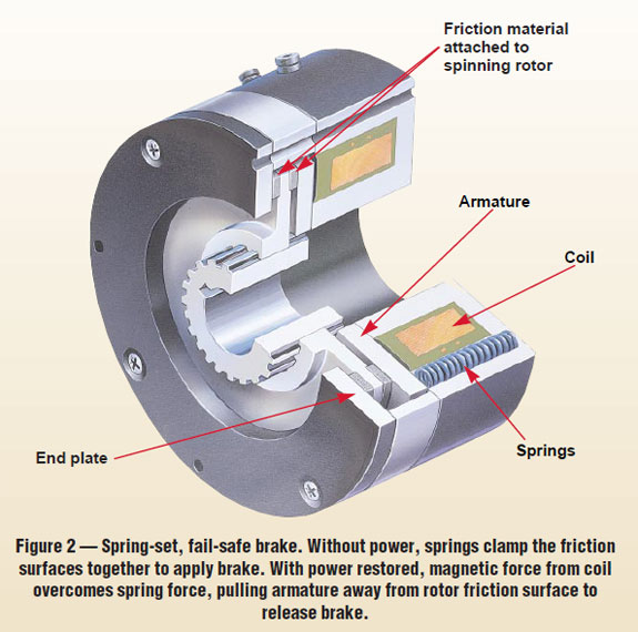
Might be biting off more then I can chew, but going to try and design a servo holding brake. Initial plan is the try and keep it 15mm thick by 25mm in dia.
When not powered will hold the servo in position.
Hope to 3D print most of it.
Ideas?
Comments?

My God. Please make this happen. I've been working on this for two years. I just had an arguement with a technician from Hitec who said he doesn't even care about the idea of holding brakes. They are compulsory. For now, I'm going to simply include torsion springs to fight gravity.
By the way, I already know how to provide power to this release mechanism at the EXACT moment the servo motor gets a PWM signal. You wont need a separate PWM channel - you can run a power wire from the DC motor inside the servo. Whenever the motor is sent power to rotate, this will send power to anything else connected to it. The microprocessor inside the servo has done all the work for you
Read some of my old posts. Solenoids are always too weak and bulky, by the way. I've tested hundreds of them. At least now your signal and power questions are all solved.
The idea of a permanent magnet with positive polarity downwards against a coil of insulated copper around an iron bar with positive polarity facing upwards when power is applied seems viable if you can set up a nice grippy stopper. So by default, the permanent magnet is pulling the grip covered coil towards it, preventing rotation. When power is applied, the electromagnet is repelled. A spring can help with clamping also.
Looking at your diagram, your 'end plate' or something near there could be made of a permanent magnet.
I will start on the CAD work tonight and hope to start some 3D printing this weekend. Ordered 28awg magnet wire this afternoon to wind the coil.
The permanent magnet in the end plate also works like a magsafe connector in my designs to connect servos together.
When power is applied, the armature is pulled down allowing the rotor to turn freely. No magnet needed. When power is removed, the springs push the up against the rotor pads and locks it in place.
Can't wait to see it working.
Hi @rz90208
Your idea is great !
If I may throw my thoughts in, If you can get a guaranteed full movement of the armature disc release, instead of a friction disc use a serrated disc. (3d printed? )(iron or metallic filament I think is available?) The teeth will hold better than friction allowing a lighter spring tension.
I have used this type of brake (industrial size) and found you need to release the brake first, even for a fraction of a second. Otherwise the motor tries to drive thru the brake causing high motor current.
I wish you luck with this idea. There is a need and it would be great to see it built.
Ron
PS. If you want, contact me at [email protected]. I have an idea how to print a semi-metallic disc with regular filament.