Asked — Edited

Servo Holding Brake

Might be biting off more then I can chew, but going to try and design a servo holding brake. Initial plan is the try and keep it 15mm thick by 25mm in dia. When not powered will hold the servo in position. Hope to 3D print most of it. Ideas? Comments?

User-inserted image


ARC Pro

Upgrade to ARC Pro

Elevate your robot's capabilities to the next level with Synthiam ARC Pro, unlocking a world of possibilities in robot programming.

Australia
#1  

My God. Please make this happen. I've been working on this for two years. I just had an arguement with a technician from Hitec who said he doesn't even care about the idea of holding brakes. They are compulsory. For now, I'm going to simply include torsion springs to fight gravity.

Australia
#2  

By the way, I already know how to provide power to this release mechanism at the EXACT moment the servo motor gets a PWM signal. You wont need a separate PWM channel - you can run a power wire from the DC motor inside the servo. Whenever the motor is sent power to rotate, this will send power to anything else connected to it. The microprocessor inside the servo has done all the work for you ;)

Read some of my old posts. Solenoids are always too weak and bulky, by the way. I've tested hundreds of them. At least now your signal and power questions are all solved.

Australia
#3  

The idea of a permanent magnet with positive polarity downwards against a coil of insulated copper around an iron bar with positive polarity facing upwards when power is applied seems viable if you can set up a nice grippy stopper. So by default, the permanent magnet is pulling the grip covered coil towards it, preventing rotation. When power is applied, the electromagnet is repelled. A spring can help with clamping also.

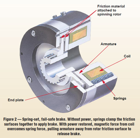
Looking at your diagram, your 'end plate' or something near there could be made of a permanent magnet.

PRO
USA
#4  

I will start on the CAD work tonight and hope to start some 3D printing this weekend. Ordered 28awg magnet wire this afternoon to wind the coil.

Australia
#5  

The permanent magnet in the end plate also works like a magsafe connector in my designs to connect servos together.

PRO
USA
#6  

When power is applied, the armature is pulled down allowing the rotor to turn freely. No magnet needed. When power is removed, the springs push the up against the rotor pads and locks it in place.

Australia
#7  

Can't wait to see it working.

#8  

Hi @rz90208

Your idea is great !

If I may throw my thoughts in, If you can get a guaranteed full movement of the armature disc release, instead of a friction disc use a serrated disc. (3d printed? )(iron or metallic filament I think is available?) The teeth will hold better than friction allowing a lighter spring tension.

I have used this type of brake (industrial size) and found you need to release the brake first, even for a fraction of a second. Otherwise the motor tries to drive thru the brake causing high motor current.

I wish you luck with this idea. There is a need and it would be great to see it built.

Ron

PS. If you want, contact me at rtnron@att.net. I have an idea how to print a semi-metallic disc with regular filament.

PRO
USA
#9  

Thanks Ron, I have some carbon fiber filament I was thinking of using for the rotor but after some more thought, I decided not to because it might make the splined shaft collar not slide smoothly. So I now plan to make the end plate of the carbon fiber and the rotor of ABS, so I think the serrations would weaken it to much being that I only plan to make it 1.5mm thick (not counting the hub). For the armature I am hoping to find a steel washer that I can drill out and use. Not sure what to use for the friction material, I considered some type of sand paper but am concerned that it will wear out to quickly. Maybe putting the serrations in the armature (thinking as I type). First hurdle will be the drawing of the splines in Sketchup.

RichardZ

#10  

They don't need to be too deep, as long as there is a locking action. Even holes vs bumps will work. Alternating radial grooves and raises could work too.(I have seen this type in action.). 3d prints can allow easy tests. Maybe making a little larger prototype will help the testing. I thought there was some iron powder base filament around.

I was wondering if you used the round hub that comes with a servo as the spline mount. Then stack your test brake to that for testing?

You can also steal the .stl file for the EZ robot Jd shoulder mount or lever, etc. and just use the spline. Modify what is left with what your needs are. I used this method to build a servo thrust bearing. It is real tough to build the spline in cad.

Ron

Australia
#11  

You should use flat grip, not teeth. The servos will burn out if the teeth lock the rotation when the servo is slightly away from it's destination.

Here's an old image of my servo brake concept from September 2015:

User-inserted image

The above image assumes pan centralisation and tilt extension have been added.

User-inserted image

User-inserted image

User-inserted image

User-inserted image

PRO
USA
#12  

That should work! On the end plate I will put .2mm ridges .4mm apart and on the rotor I will do the same. Then the 2 sets of ridges will interlock. This could save me several millimeters. Great input Ron, Thanks I picture the splined shaft as a solid plastic rod with splines running the length of it. on one end is a 4.8mm hole that I will heat up an old brass servo gear and press it into, making the servo side splines. on the other end, the rod reduces down to the same as the servo. I picture it being assembled by putting the shaft on the servo, sliding the brake assembly over the shaft, then putting on an over sized servo bracket. I plan to print some tabs on the bottom of the brake assembly that will hold against the sides of the servo to keep it from turning. If the splines end up being my biggest hurdle, I think this should come together quite nicely.

RichardZ

Australia
#13  

The worm gear is the ultimate holding brake of course, but it requires about 14 times higher servo speed. Here's a gearing idea I drew a few months ago for a high speed continuous rotation servo with centralisation and worm gear mod.

User-inserted image

#14  

Another concept. I had an idea of a scissor disc brake. A spring applies tension to clamp the two scissor brake pads against the disc. A solenoid pulls the scissor open to release the tension. This simple mechanism and can be mounted on the side of the servo.

Just a thought.

Ron

PRO
USA
#15  

@Zxen, After some thought, I see your point, Sense the rotor is free sliding, it could slide and catch ridge on ridge and cause current spikes. yup back to friction pads. @Ron, I think I have an idea how to draw the splines, I will post tomorrow how it goes.

RichardZ

Australia
#16  

@andy roid, I have tried a LOT of solenoid and spring combinations and they simply don't have the strength to pull back against a spring that's able to clamp against gravity. A solenoid is a much smaller version of what @rz90208 will effectively be creating by winding a lot more insulated copper around an iron doughnut. It is an extremely fiddly operation - even trying to sand down the tips of the insulated copper so they are not insulated before trying to neatly solder them to the power terminals that come out of the (here's six months research for free -) servo's internal microcontroller outputs is a massive pain.

The other anti brake/holding brake/ that would work effectively is a second servo that has its own data channel, but this would require you to painstakingly code for it to pull the spring back each time you want the primary motor to move. Its probably the most foolproof idea. You can't just use a Y splitter on the servo and brake servo because the brake servo would move in both directions. A mini linear actuator servo needs power at all times but would not require a spring. A mosfet rc switch is extremely problematic in that it usually needs to receive a PWM signal that is equivalent to 50% rotation before it activates - solenoids won't even move until the signal is strong enough, and servos will barely pull the spring until a high threshold is reached. This is why a servo on its own data channel should work against a spring, but you want it to be very small.

Something that pulls the spring back with 100% force that activates whenever the servo's DC motor is sent power by the servo's internal microprocessor is definitely the most automated and compact method, so long as the servo's internal components and wires can handle the current. A magnet with enough coils to achieve this and to do it smoothly will take some very fiddly engineering. There is also the question of whether you want to clamp a disc (disc brakes) or press against the inner wall housing (drum brakes) or press up against a disc (connected to the rotating lid in a pan servo or perhaps tension a belt in the case of a tilt servo).

The tension in a dentist's light is outstanding. If the spring's tension were to be descreased then the arm's joints would become floppy (rotate freely). In terms of the belt idea, imagine a cheap exercise bike that uses a belt of fabric around the wheel that you are pedaling. When you tighten the tensioner, it does not want to move. I'll draw that idea now using a standard hobby servo:

User-inserted image

A spring needs to be added to this image so that the tension is pulling (or pushing) the holding brake servo outwards. The holding brake servo must move inwards to fight the spring and relieve the belt tension. In this pan servo, I have centralised the shaft (because off-centred shafts are useless). In the case of a tilt system, the configuration would not need the centraliser, but the same method could be used just as effectively.

User-inserted image

This idea is very bulky and requires extra coding, wiring and also sacrifices a data slot for every holding brake servo. Hopefully its triggered some practical ideas.

#17  

Here is a quick thought of the idea that popped into mind this morning for the mannequin you are working on.

Forgive the horrible art skills, :)

But, you can get the idea of what I am thinking by looking at E1 and E2 and using that in place of the discs used in the image.

E1 acting as a claw/brake by its teeth locking into the gear E2 and holding it in place.

User-inserted image

#18  

I am assuming, a small simple cheap servo could be used to control the claw to lock gear into place if the teeth are set in a way that there is a slight hooking action to prevent slippage.

It's a simple thought.

#19  

Ok, i will let this be my last thought on it for a bit while I go back to working on other things. But even a cheap linear actuator put behind you servo or somewhere convenient to push an arm with an end shaped like a crescent moon with teeth to push toward the E2 gear locking into the teeth and holding its position. Covering a wider area of teeth and preventing slippage.

PRO
USA
#20  

I believe I have come up with a much simpler servo break. I have not tested it yet but have ordered a couple of the solenoids from sparkfun.

the idea: I will 3D print a cog that will go on the servo shaft, the top will be the same size as the shaft so as to still accept what ever needs to attach. I will also 3d print a end piece for the solenoid shaft that fits into the grooves of the cog. When not powered the solenoid keeps the servo from turning, when powered will pull back and allow the servo to turn. Link to the Solenoid: https://www.sparkfun.com/products/11015#documents-tab

My only concern is, will the solenoid be able to pull back when it is holding a weight such as an arm elbow servo.

#21  

Place a command in your script to raise the servo just enough to take the weight off the pin then pull it back with a second command.

PRO
USA
#22  

I thought of that after sending the post. For the cog, I am going to try and use the Nylon drive gear from an old servo. Drill the bottom then use heat up a brass drive gear and press it in to make the splines.