
rgordon
Sabertooth 2X12 R/C Success
Hello all. I have been very busy lately but I finally got a few weekends to work on the robot.
I have poured over the forum and web trying to find a way to smoothly change from EZ-B control to R/C control and back again. From what I have read, it seemed others were having this issue as well. I have looked at all the tutorials and contacted Dimension Engineering, tried every possible combination of dip switch setting and EZ-B control but could only get it to work in one or the other but, not both...until now. 
I decided what I needed was a way to electronically select between two dip switch settings. A sort of dip switch configurator (for lack of a better term). So I searched until... I think I found the end of the internet.
Maybe I missed something but there did not seem to be one available...so I did what any good robot nerd would do...I built my own.
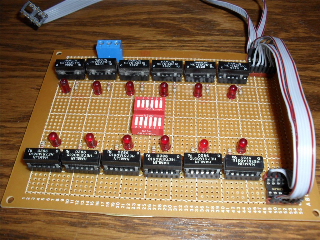
I used tiny HE751A0510 reed relays with normally open, SPST (ie. single contact). The ones I had on hand happened to have 5V coils with a suppression diode. For now, I constructed it on a perforated circuit board. Eventually I will try to miniaturize it further and etch my own board. There are two separate circuits. Each circuit has six relays and one six position dip switch. Each relay contact represents one dip switch position "on the Sabertooth". Each relay has its own L.E.D. to indicate when it is activated. The dip switch on the circuit board is used to energize a relay or can be left off if need be.
Now the tricky part. I had to de-solder the surface mount dip switch that is on the Sabertooth. I had quite a time to get it to come loose. I used solder wick to soak up the solder off of each tiny pad and finally it popped loose. None of the dip switch legs go through the board. I placed a small bit of fresh solder on each pad. I then took an IC chip socket and cut it down so it only had six pins on each side. I bent each leg so that it was shaped like a tiny foot. I pre-tinned each leg with solder. (This makes soldering easier and quicker). I placed the socket on the Sabertooth pads and proceeded to solder each leg in place. I used another IC socket and some ribbon cable to make a jumper from the board to the new Sabertooth socket. I needed a way to remotely switch between the two circuits so I purchased a Battle Switch from the Robot Market Place web site. It is an R/C controlled SPDT relay. You just hook it to one of your (on/off) R/C receiver channels. I chose the AUX channel that is normally used for R/C airplane flaps. The AUX channel is toggled on/off via a switch located on my Spektrum DX6 transmitter. I installed a three position terminal block on my dip switch configurator board. I hooked 5V to the common terminal on the Battle Switch relay and ran wires from its two contacts to the dip switch configurator board three position terminal block and hooked the two 5V wires to the outer terminals and GND (common) to the middle terminal. Each of the circuits share the GND connection.
Also I have installed a R/C Mux circuit from RobotShop.com. It has two 8 channel inputs and one 8 channel output that allows me to hook all of the R/C receiver channels to its "B" input terminals and the Digital out from the EZ-B that I am using for the Simplified serial to the Sabertooth and the Digital out(s) I am using for the Head pan and tilt servos to its "A" input channels. The 8th channel of the "A" input is used (defaulted by the manufacturer) to select which inputs go to the output. If no signal is detected on this channel all of the "A" inputs got to the outputs. The AUX channel from the R/C receiver that goes to the Battle Switch relay is also hooked to this channel 8 via a Y- cable.
So now with the flick of a single switch on the Spektrum DX6 it will smoothly set the Sabertooth dip switch setting to whichever I need for control; EZ-B control or Spektrum R/C control. BTW the Spektrum DX6 has an approximate range of 3000 ft. It does not have to be this model. You could use most any R/C transmitter as long as it has at least one on/off channel and a few other normal servo channels to drive and steer with.
I know all of this sounds complex when describing it but, it will make sense when you see the schematic and photos (and hopefully a video). I will post all of this tomorrow. For now it is bed time. Good night my robot friends. sleep

Here are a few pictures of the Dip Switch Configurator Board I built.
Right now its kind of large but, I hope to scale it down alot when I etch a circuit board for it.
Here is a close up of the Spektrum BR6000 R/C receiver and R/C Mux and EZ-B.
Picture of the Battle Switch. (not mounted yet).
Front shot of the robot upper deck.
I'll be posting all the other pictures of the robot project in its own thread soon. Also I am working on drawing a schematic for the dip switch configurator board and a wiring diagram of how it all hooks together.
Today I installed the ping radar and have been playing around with config settings. All seems to work well.
The fastest scan setting still seems a little slow but, maybe after a few more tweaks all will be good.
Here are a list of questions I am trying to find answers to:
Anyone have any good advice for using the ping radar?
What is the best height to place it on the bot? How many inches above the floor should it be mounted?
Should it point straight outward or should it be angled downward slightly?
Is there a restriction on how many other ping sensors can used? Say if I wanted to mount non -moving pings at various locations around the perimeter of the bot to detect if he is getting to close to a wall or something else.
Thanks
bump