
dkennyken
Hi all, I'm new to this forum and new to building robots.
Got some inspiration from DJ Sures 1980's Omnibot build.
I've got myself a EZ-B v3 control board and an old omnibot but was wondering if there is a way to purchase the rest of the kit or at least the wifi camera for v3?
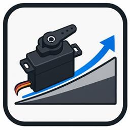
If not any advice on the best servos to use would be appreciated. I have been looking at AS-17 servos and HXT 900s.
Thanks for taking the time to read my post and hope to hear from anyone soon
Ken.
Nice to see another omnibot enthousiast
There is no camera specific to the v3 board. Whatever camera is recognized by ARC will work. My omnibot has a PC on-board so I'm using a wired USB webcam. The camera that DJ is using in that video is a wireless USB cam. It used to be sold in the shop here, but you can still find it on ebay.
For the arms, I'd suggest you go with a metal-geared servo that can lift at least 5kg/cm.
If you're planning to make his head move, you can just use a normal plastic geared servo.
Here's my omnibot thread, but there are lots of other people on here with their own omibots
I saw your omnibot on youtube some time ago and was very impressed.
Can't wait to get started.
Good to see you got to follow your passion at EZ-Robot.
Hopefully I'll get my omnibot on par with yours and DJ Sures eventually lol.
Thanks again.
As Niek suggested, you can use any camera that is recognized by ARC. We will be putting a few of the old cameras back up for sale in the not too distant future as well. Along with that, you'll be able to buy the HDD Servo directly from the store as well.
The HDD Servo's are the ones that DJ used for his Omnibot build.
Alan
So I've put together a shopping list for my build can anybody give me some input on the parts I've listed?
Glue gun,
2×MG-995 digital servos,
2×opto switch QRD1114,
Duel bridge DC stepper motor drive controller board L298N,
1×As17 servo,
Blue wireless 2.4Ghz camera,
3× HT900 servo,
Ultra bright led's (not sure which size I'm gonna need 3mm/5mm or 10mm?)
Have I missed anything?
I was going to use the 6v lead battery that came with omnibot, is that a good idea? (It's actually a brand new replacement).
Also I have a sensor to scan for objects in his path do I need to get an attachment to make it scan from left to right?
Also will I be best powering the ez-b board from the battery attachment that came with it or from the lead battery?
Sorry if my questions are daft, this is all very new to me, I'm afraid I'm a total noob lol.
Outside of the jack from the battery needs to be ground for the EZ-B which is backwards to how Tomy set it up with the Omnibot. Connecting it backwards to a V3 can blow the regulator.
Also, it may pay to build a few TIP Transistor Switching Circuits if you plan to turn lamps on and off.
If you struggle to find anything you need feel free to give me a shout, I've compiled a list of online stores in the UK which stock most of what is needed and a list of problem free ebay sellers from China if you want to go cheap.
Where in the UK are you from just out of interest?
I'll certainly take the advice given, not going to order anything until I know 100% what my plan is, I think more research is in order lol.
I live in Manchester Rich, I'll let you know if I'm struggling to find any of the items I need ta.
Thanks again, will keep you all informed
Female to Female suitable for 0.1" spacing is what you're looking for.
I have used servo/accessory extension cables before and just snipped off the one end, soldered direct to the board (or joined two together to make female to female 3 wire cables). These are cheaper but be cautious of cheap Chinese ones as they can make sensors act up.
Will keep you all upto date on things as and when they progress, and if I need any advice I'll ask if thats okay.
Pop Turnigy 2S 5000mAh LiPo in ebay and check out the prices, from memory I think the last 2 I bought were around £20 each.
id=271300699584
Any opinions?
Yeah I was looking at that very one earlier today. Auto cut off, small and 4000mAh so it should be fine. The only concern I'd have is I can't see that it has a balance port which could mean unbalanced charging and reduced life, but it's not that big of a concern to be honest.
Edit: My mistake, it looks like it may have the balance plug after all.
They both cost about the same. I suppose it's a choice between size and mAh?
I may need the extra space
Been ordering quite alot lately will update my shopping list in the near future.
Now It's time to start updating the robot shell whilst I wait for all my parts to come.
Sorry for being such a noob but how does the balance plug work? And how would I know if it has built in monitoring?
it is a trade off between size and capacity. 4,000mAh should be plenty, I use 5,000mAh in Melvin and he lasts days before requiring charging.
The balance plug...
The LiPo battery is 2 cells in series. So imagine 2 AA batteries in series, you have your -ve, +ve, -ve, +ve. From the two outer most terminals you have the combined voltage of both batteries, or cells. That's great for powering stuff but not so good for charging.
The balance port is 3 wires, one from the outer most -ve terminal, one from the outermost +ve terminal and the third from the middle of the 2 cells, where the -ve and +ve join to make it series.
Using this plug the charger can monitor each cell's voltage and charge the battery in such a way that cell 1 and cell 2 have equal voltage, or are balanced.
This probably explains it a lot better than I can.
Thanks for explaining it for me, made perfect sense.
Am I right in thinking that the ez-b will only use the amps it needs to power boards, servos and camera and wont use anymore than that?
good Luck!
Much appreciated for all the advice, thanks.
I'll take a look at the tutorials.
Here's the links to them, any opinions please?
http://www.tjshobbies.co.uk/product_info.php?cPath=22_32_67&products_id=83
http://www.tjshobbies.co.uk/product_info.php?products_id=644
Then it's a visit to the robot spa
Tip: Don't put the dome in the dish washer, mine scratched Melvin's visor. Cool and gentle wash, not the thorough one, you don't want to melt it
Didnt bother with dishwasher tabs.
I have another omnibot not comunicating with the remote which is in need of a transplant.
Its shell is in nice condition, it's not lost it's colour so I will be fitting this board inside it and keeping it original
and I've ordered a motor driver 1A duel TB6612FNG to control the original omnibot motor.
I've got IR sensors QRD1114 and HC-SR04 sensor on the way aswell as various resisters and cables and servos.
Do I need to order a voltage regulator or can most things connect straight to the ez-b?
Also I may just stick with my 6v 4.5 Amp omnibot battery for now and see how it goes.
If V4 you will need to regulate the HC-SR04 to 5V.
If V3 it's already regulated.
Not 100% sure on the TB6612FNG, mine is wired from the V3 so +5v but the V4 doesn't regulate so will be battery voltage. I'll check the datasheet when I get home.
Servos you will need to check. If they are the EZ-Robot ones they will be fine on anything up to 7.4v otherwise you may need to regulate to 5V or 6V.
So will I be ok to wire the TB6612FNG straight from the V3 EZ-B board to the motor?
My MG-995 Digital servos use 4.8v to 7.2v so they should be okay I presume and my HXT900 servos for his grippers use 3v-6v. I also have a AS17 for his head.
Thanks again, your help is very much appreciated... I've got so many ideas for my bot just need to not try and do too much at once lol.
The TB6612FNG is fine to use however you need to use an external supply (i.e. don't take the Vm from the EZ-B take it from the battery) for the motors. I have also had some issues with Melvin spinning on powering up, I believe my V3 sets some pins high when initially powered up on occasion, I still need to check it properly though before I can say anything for sure. The TB6612FNG as wired like this works fine on the V3.
The MG-995s I found were browning out my EZ-B when the 2 in the pan/tilt of Melvin's head were being used. I found I needed to add in a regulator and provide them with power (Vcc & Ground) which didn't pass through the EZ-B. I have since made it a standard of mine to provide all servos Vcc and Ground from regulated supplies rather than from the EZ-B (basically only bringing the Signal from the EZ-B, the power comes from the battery via a regulator).
Good luck trying not to do too much at once. Melvin was supposed to be me testing the water... I fell in the deep end very quickly and have been juggling projects ever since.
so the servos should work fine straight from the 6v 4.5 amp battery with a regulator for each one? What do you think of the LM2596 regulator board? Will that do what I want?
Once again thanks, it would have taken me forever to try and work out the wiring for the motor controller.
Run out of time tonight (it's now midnight so I need my bed!) but I also found my original sketch version of Melvin's schematic. I'll scan that in tomorrow and pop it up for you.
Would searching 1602 cable on ebay find me the correct peripheral connector?
Also although it would be good to hook it up to the ez-b If thats not possible could I put in an sd card with animations on or even link it to my raspberry pi to play animations?
A heart beat reading would be cool (hospital heart monitor style) especially if it could monitor the battery?
Can anybody tell me whether the lcd display will run with ez-b and which type of lead I'm gonna need?
Before you buy any display make sure you can get a decent datasheet for it. You will need to know the commands to use to send the data to the display. I've had little luck with ebay displays since they usually come from someone who doesn't speak English and don't come with Datasheets.
It looks like it can be either Serial or I2C. Which means, if in serial mode you can use a simple 3 wire extension connected to a digital port of the EZ-B and use the SendSerial() command to send the data to the display. If using it in I2C mode you need 4 wires connected to the EZ-B's I2C port.
How to use it is the main question, you will need to know the serial or I2C commands to send data to the display. It's not as simple as putting SendSerial(D0, "This is text"). There are usually a bunch of commands needed to set the cursor position, then display the text, then exit from text display mode...
Get the datasheet (not the Arduino code, that's usually pretty much useless to us) before you buy anything.
If you only want to display text then I always recommend using Devantech LCDs from Robot Electronics Link. These are what I always use, they are simple to use and are of a very decent quality. They also have the ability to set up custom characters (see Melvin's battery monitor display for an example).
Link to the ebay item or post the item number and I'll have a better look at it when I get the chance.
Item number is 261281402779.
If it gets too technical I may just put my samsung gs2 phone inside it instead or buy a monitor from Robot Electronics
I've asked the seller for a data sheet, I used google translate lol.
Also ordered a blinkm smart LED, probably for in his head although I may fit it in his chest?
The other one you put a picture up of does have a datasheet with the commands required. Looking at it, it's very similar to the LCD I already have so it should be pretty straight forward to use. I ordered one (it was only £10) so will let you know when it turns up.
BlinkM is simple to use, it's natively supported by ARC and easy to script too, I think I've done a bit of a tutorial on it (or it may have been just a few examples). Awesome little bit of kit
I've asked the seller for a data sheet and if not a refund.
Silly me!
Is there a specific connector I can get to link them all to the same power source? Or am I best making some sort of board that links them all together or even using chock blocks?
On another note I've managed to cancel the lcd and get a refund
Don't forget to get jumpers too so you can distribute the power to multiple posts. These can handle up to 30 amps of current so your good with these.
Personally I would do it this way...
Reuse the existing flylead from the omnibot however cut off the spade crimps, strip the wire back, swap them around (Tomy used a centre ground, EZ-B uses outside ground), strip 2 more cables and crimp both in to one spare connector to make a Y cable (or use piggyback spade connectors)
Plug the barrel jack in to the EZ-B
Connect the other cables to a piece of Stripboard using
16A PCB Terminals. This leaves you with 2 strips with 0.1" spacing that you can now use for battery Vcc and Ground.
Solder in some pin headers and you now have a modular board which accessory extensions, jumper cables, servos etc. can plug directly in to, and be removed when needed if you wanted to make changes, add in things, borrow things for other projects.
Everything remains modular. Very little needs cutting and changing and it leaves everything the ability to be changed easily, removed or borrowed for another project (and believe me, you will borrow from one project to get another project moving).
I read a post from a while ago where you were going to hard wire jumper leads to the v3 blue wifi camera straight to the board inside rather than the usb connector, I just wondered how reliable it was doing this and did you have any problems with the battery removed or any other problems?
EDIT: @Rich I've only just seen this post, what a great idea, I already have all the parts needed so think I will go with this
Niek answered my original question but Rich provided lots of valuable information aswell as other forum members.
It has lots of useful information for beginners in building robots, like me lol.
Thanks everybody
It works. It's very similar to the digole LCD I picked up earlier in the year, the commands are the same, the datasheet is the same datasheet... it even shares the same I2C address (when put in I2C mode).
I'll cover it in a new topic when I get chance.
Long and short of it is this though (my opinions on it).
Small... very small. It's only 1.8".
16x5 character text display, which is just about big enough for basic info but I prefer bigger to fit more in.
Graphics commands can be a bit of a pain to use, the rectangle (filled and unfilled) seems to only draw an unfilled rectangle which is pointless.
bitmap graphics, while they work you need to convert the image to bitmap data, each byte is an 8x8 grid of pixles. There is a converter on digole's site but this brings up another issue, you can't send enough data to the LCD over I2C in one go, so the image must be split in to parts. Easy enough to do but it's more code and a pain to do if you don't realise.
I wouldn't recommend this one to be honest. Unless you needed some very basic graphics and a screen 1.8" in size (which may come in handy).
It all depends what you want to be able to do on it though...
I'll upload a video too so you can decide if it looks like it'll do what you want it to do.
FYI, a sample piece of code to display a small battery symbol, split line by line to avoid the maximum data transmitted to I2C limit;
Code:
Imagine having to do that for every graphic you want to use...
I may give this one a miss for now.
I've seen some small low voltage two wire multimeter displays that hook straight up to your battery, I may use one of these until I feel brave enough lol.
It's gonna be enough fun figuring out the coding for the ir & ping sensors aswell as other functions
*blush*