I have a problem with the MMA7455 panel in ARC normally ARC connects fine but if I add the 7455 panel it locks up ARC on connecting to the EZ B board and I have to use Windows task manager to shut it down and start again. It has worked for me but only a couple of times

Thank God for that, I thought it was only me who had that happening. Mine was working fine but sometimes it doesn't. I just thought I had wired it up wrong again or it was because I have other I2C devices running too.
I plan to look into this one this weekend to see if I can work out what I've done since it worked and since it stopped working but hopefully someone can give us a clue.
Rich I've re-wired mine but that's not the problem. Nothing to do with the EZ-B board but I noticed if you disconnect the +5v to the MMA7455 it still lights the LED! don't know how that's wired appears to be getting power from the SCL and SDA lines totally weird
A few times in the past I've let the magic smoke out of ICs by plugging them in while the power was turned on.
Is there a chance Rich baked them that way. Mine is working fine even with all the wires being 12 inches.
Bill
I've never plugged them in while it was powered up. Even if I had done so by accident the spare one has been barely used and I am certain has never been plugged in while the power is on.
Also @winstn60 has the same issue.
Mine were working originally when the only control was the MMA control, but when I add the control to Jarvis it either freezes ARC up which requires task manager to kill and a power cycle of the EZ-B or if I add it before connecting to the EZ-B on connection ARC will disconnect as soon as it connects and freeze up with task manager being the only way to kill it.
This happens on 2 different MMAs and on 2 different PCs, while connected direct to the EZ-B or via my I2C header board.
I haven't tried a new project with no controls again yet, I will try that later and see what happens.
For awareness the MMA7455 needs leads at least 6 inches long. I tried short leads 3 inches and it just would not work on the SCL SDA lines. Probably the extra pf on the line helps stop ringing on the pulses. Playing around with pull up resistors just seems to produce inconclusive results
I take it the new update solved this one then? I haven't had chance to check since my PC took a nose dive last night so is currently in bits until the replacement parts come Saturday (was time to upgrade anyway).
My leads are around 4" and it had worked on them without any pull ups. From what I can make out the MMA break out board has pull up resistors on it anyway...
Rich the update has solved most of the issues just a problem remains if the BT connection gets lost for whatever reason. Which is why I haven't closed the question. Bad news about your PC I get very little time to play with this stuff since the arrival of a new baby 2 weeks ago!
Still getting the unresolved forum thread email for this post
You need long leads at least 6 inches for the MMA 7455 to work
Crediting Rich with the fix to see if I can get it to go away
confused
Hello there,
I'm struggling with that problem discussed here.
As soon i activate the MAA 7455 (connected with the i2c) Module in the software the EZ-Board and software freezes.
i really want to use the mma7455 but i cant see whats wrong. the length of the cables are about 7 inc.
any ideas ?
Is it connected to the EZ-B correctly?
It is a very sensitive piece of equipment and cable lengths are very important, if they aren't right then it simply wont work.
And the EZ-B V4 will hang and freeze up on any I2C error (the manufacturers of the main processor designed it that way).
Keep trimming back that length and retesting is pretty much the option here. As previously stated, mine were about 4 inches long when I was testing out the device on the EZ-B V3.
thanks for the fast response!
thats properly it !
i used different power connectors (3,3V and ground from the Ax row).
..now i have shorten the lines to about 2,5 inches but its still freezing the board.
should i use the power pin's of my used SDA/SCL port ?
@Julius are you using any pullup resistors from SDA and SCL to 3.3V? If not, toss in some 4.7-6.8kohm resistors to see if that'll help.
i tried this :
2x2 10k ohms in parallel.but nothing different than before. again ez board freezes as soon as i start the i2c maa7455 module in the software.
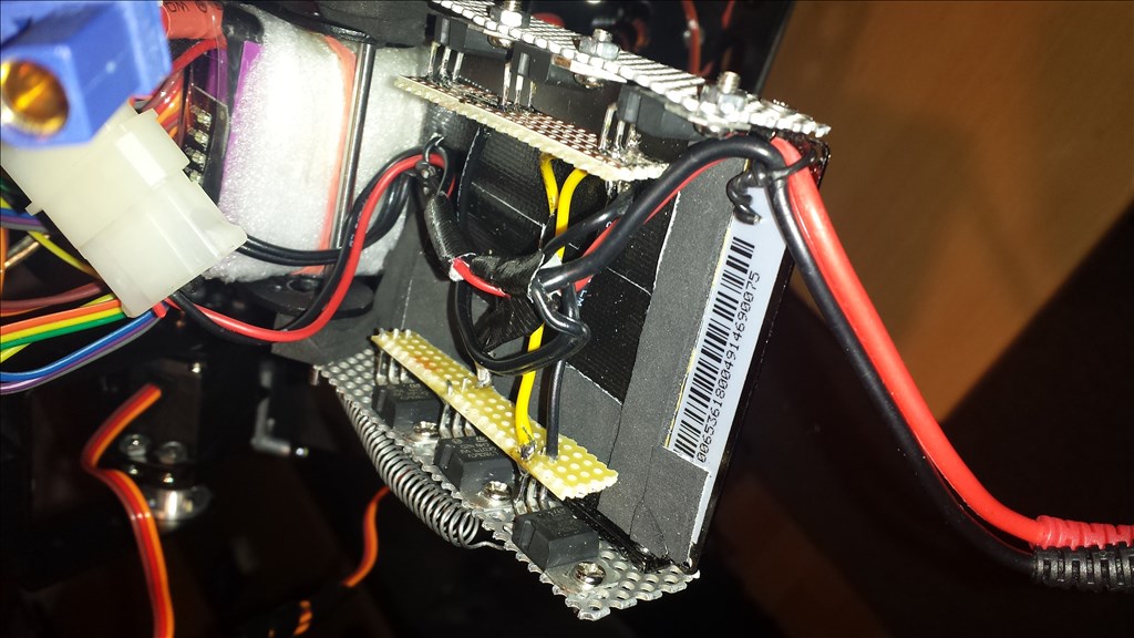
here is the set-up:
(red = 3.3 V, brown = ground, blue = SCL, green = SDA)
Hi are you using this as a G meter for your car? If you have an Iphone you could try the sensor streamer app (was a free download from the apps store) that sends data straight to your PC and gives you an accelerometer for 3 axis. DJ added a panel to ARC for it.
Otherwise try longer wires to the MMA7455
@Winstn60 Actually I'm sorry to contradict you but shorter wires are better when dealing with I2C, due to lower line capacitance.
@julius I can see that you are using 3.3V from the ez-b going into the onboard 3.3V regulator, this might be dropping your voltage down far enough to make the sensor communication unstable. (Thanks for the photos, it definitely helps)
Hi @Jeremie contradict away but as I posted 1 year ago I had to increase the wire length to get it to work go figure confused
Interesting...I've always had better results with shorter wires, well it never hurts to try both I guess.
Hey there,
its no car. its a bi-ped. robot and its looking atm like this :
the MAA7455 should go somewhere on the hips.
i have no iphone, but i'll look for something simular for android.
longer cables will be next.
i might soon get me an oscilloscope, so i'll get a closer look to the levels and timing.
@jeremie should i try to "pull up" with 5 V ?
..for that i need to throw in a 7805 for the regulated 5 V
atm I got 6 x 7806 already in it for 6 V, 5 A max for the servos.
so there is :
(they get warm at 5 A max, 2 A average when moving.. they got a small heat-sink by now!)I read a bit about I2c spec's. this might be interesting: (en.wikipedia.org/wiki/I%C2%B2C)
the SDA/SCL levels should be 5V or 3.3V (but it works with something in between) with pull resistors ! the "low level" is under 0.5V.
the I2c network stops, if a device is not working properly. (so we had that already)
....and also by the total bus capacitance of 400 pF, which restricts practical communication distances to a few meters.
I wouldn't suggest pulling up to 5V, as it would damage the accelerometer.
I didn't realize (until you sent the pictures) that you were using that style of application board. That board has pull-ups already on it, as well as a linear voltage regulator.
The voltage regulator will drop the voltage from 3.3V that you are supplying it to somewhere around 2.8V that powers the accelerometer. You may need to by pass the regulator.
I have the same boards at the ezrobot shop, I'll try to do a test tonight.
i thought that. that would be helpful !
i just got 2 new ones on ebay.. this will take a while. maybe mine is just broken. its produced alright, can't see any loose resistors or something..
I was able to get some testing done tonight. I had the MMA7455 board working with the EZ-Bv3 but could not get it working with the v4 yet. There are 4.7K I2C pull-ups on the v3 board so I will need to fiddle around a bit with pull-up values and wire length to work with the MMA7455 board. I know I had it working in the past I just don't remember what I had to do. I think I may have used the LED eyes plugged into another I2C port to leverage the pull-ups it had on board, I will have to do a bit more testing tomorrow.
If you have a v3 board you could test your MMA7455 with it to see if it is working as the v3 board is less picky about I2C.
Hello @Julius,
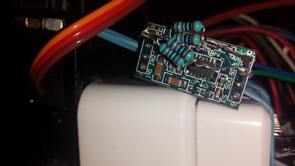
I have a late Christmas gift for you, I was able to get the MMA7455 accelerometer board to work reliably with the ez-bv4. Here's how I did it:
Used short wires connected from one of the I2C ports on the ez-bv4 to the MMA7455 sensor board
Soldered 4.7Kohm pullups from the SDA and SCL lines to 3.3VDC (these are possibly optional since there seems to be pull-ups on the board)
Soldered a 1nF ceramic capacitor from SDA to GND
Here's some pictures of my setup:
You may not need to, but I removed the voltage regulator from the board and shorted the voltage input and output pins so I didn't have a voltage drop (through the regulator) when I provided 3.3VDC to the VCC pin.
Thank you so much for your effort !
I will go through this today or on weekend.
were is that nice i2c-connector-plug from ?
thanks again! a nice Christmas!
No prob, that I2C connector is from our shop
https://synthiam.com/Shop/AccessoriesDetails.aspx?prevCat=9&productNumber=101
Edit: I forgot to mention that with you current setup you may just need to solder a 1nF cap from SDA to GND on the board and have it work.
I tried alot. got me new 1nF caps, but its always the same. ..as son the software-module for the maa7455 is starting it freezes all.
i still had a maa7361. now i'm going into the analog inputs with a X,Y and Z signal instead of the i2c line. its way more cables but its doing its job with a tiny bit of code.
thanks for your help anyways! Have a good start into the new year !