Robotz012248
L298n Motor Driver Question
@ DJ or anyone else:
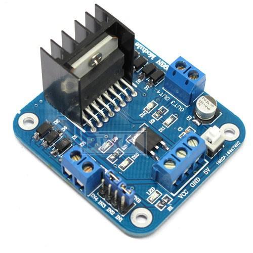
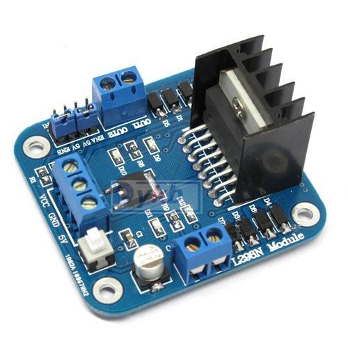
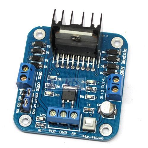
I need some clarification on the hook ups for the L298N, if you please. DJ, you answered my first question about this motor driver in my original post. I understand the IN1, IN2, IN3, IN4. To digital "trigger" pins;( like: D1,D2,D3,D4). Its the PWM I a bit confused on. In your first answer you said "connect "one" pin assigned to a digital port,PWM, trigger (like D19 for instance)" and connect that to one "enable" pin (like ENA) and that one PWM would control both enable pins. I then watched your video tutorial on PWM and in that video I see you connected "four" pins to the enable pin outs. (So I presume they are connected to ENA, +5, +5, ENB ??) and then these were connected to four digital trigger pins (like D19, D18, D17, D16). See why I'm a bit confused? I've attached another pic of the L298N I have, just for clarification. Thanks in advance. Lloyd

I have 4 of these coming so I would like to know too.
if you have 4 control lines they can hook up to 4 digital pins ,each pin is pwm control another way is to use 2 control pins IN1 GOES TO V- IN2 GOES TO V+ AND 2 other pins are digital pwm another way is to use circuit i made to go reverse and forward with 2 digital chips and have a digital pin PWM another other DIR using a digtal pinHBRIDGE.zip i design h-bridge circuits and servo circuits in the hbridge zip file chech out PWM TO H BRIDGE BMP file only need the cd4081 part circuit ,it have 4 wires comming out and 2 pins going in,can use the enable circuit if you want too