
msriddle68
USA
Asked
— Edited
I2c Response Not Recognized
I am trying to connect my IoTiny to an Arduino Pro Mini via I2C. I am able to successfully write for the IoTiny to the Arduino but when I try to request a response from the Arduino the data see corrupt.
I've tried very basic ez-script:
print(i2cRead( 0, 0xA,1 ))
And Arduino code:
  String outtoezb;

  outtoezb = "R";

  char  tempout[outtoezb.length() + 1];
  outtoezb.toCharArray(tempout,outtoezb.length() + 1);

  Wire.write(tempout);
  Serial.print("Response Sent: ");
  Serial.println(outtoezb);
When executed I get the follow on the IoTiny:
Start
>
Done (00:00:00.0230307)
And I see that the request get through to the arduion:
My i2c address: 10
Response Sent: R
Any thoughts?

You are not sending an ascii string. You are sending an int or a byte or what ever tempout is.
If you look at the variable watcher, and read the data into a variable, you will see it's not an ascii value.
You're expecting a string holding a number - but it's an int value. see in your arduino code where you convert the int to a string to view it with print? Well, you'd have to do something similar in ARC.
However, Because you are not sending ascii, the incorrect i2c read command is used. Use the i2cReadBinary() because it's not ascii.
There's examples of communicating with an arduino in the learn section user tutorials. But Ive pretty much answered the question
I've simplified the code even further. In EZ-Script I wrote:
and the Arduino code simple has:
the variable watcher returned $msg as " "
I then replaced the EZ-Script with:
and the Arduino code was the same. This time the variable watcher returned:
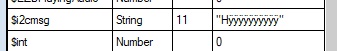
$msg[0] as 0 $msg[1] as 255 $msg[2] as 255 $msg[3] as 255 $msg[4] as 255
I tried the code from the Arduino example with the same results. Again, writing data via I2C from EZ-Script to the Arduino works fine.
Oh, and i believe with i2c you can't simply read without writing first. Doesn't the host need to write an address? And the slave returns a value for each ACK?
Looks like your trying to use i2c as a serial connection.
Let me find an example for you. I know I made one for someone before
Yeah, apologies for leading you on a wild goose chase. I wasn't thinking clearly on my previojs responses because I've been doing yard work today
So your code is trying to use i2c as if it is a uart connection. And that won't work, as you see. The arduino is a slave, which means it must send data as requested. It doesnt simply send a string, because that's not how i2c works
take a look at this URL. The Slave code is what you want to see. It demonstrates the interrupt that is raised on the arduino for queries of a register: https://forum.arduino.cc/index.php?topic=38411.0
The i2cRead() on ARC can still be used if you're responding with ascii. The arduino code responds to the register query from the interrupt.
I can write some more code for you, if you want to post your complete arduino code. Because what I feel you are doing is wanting the ezb to query the arduino for sensor data? Specifically temperature?
I was just putting in the main commands of my code, not the whole thing which looks like this:
I'm pretty sure that it is implemented correctly.
No - that won't work at all. There's a 100ms delay and the logic isn't logical . The i2c will timeout below the 100ms delay. If you read about i2c or checked the link i provided, there can only be one byte sent per request. i2c doesn't have a buffer. Again, i can't stress this enough but i2c is absolutely nothing like serial uart.
This is more like it...
These links will help a bunch - it's good to know how i2c works, because once you know, it'll make a lot more sense.
In the learn section for the ez-b/iotiny there is an introduction of port types: https://synthiam.com/Tutorials/Lesson/72?courseId=4
The i2c description on the above link provides a link to addressing here: https://synthiam.com/Community/Questions/322
The above link has a More Reading link that points to here: https://www.robot-electronics.co.uk/i2c-tutorial
The link #3 is the best for a technical understanding. But it might be too much to dive into right away. So start with #1, #2 and then #3
When the master (ez-b) sends a request to READ, it sends the register that it wishes to read, and the slave sends one byte. If the master requests to read more than one byte, the master will continue reading with an ACK. Each ACK means "i'm ready for another byte".
Unlike Serial UART, which is what you're attempting to reproduce, i2c doesn't have an input buffer. In fact, there's no way for the slave to SEND data to the Master. The master must request data... one byte at a time.
i2c was created to access memory. Think of an eprom - a master can request to begin reading at a specific address and each consecutive read from that request will increment the memory address by one.
So if the master requests to read 0x20 with a size of 5... The master sends the slave address with a byte that says "i'm going to read from you". The slave then puts the data stored in memory address 0x20 on the wire. The master receives it. The master sends an ACK, meaning "i want another byte". The slave puts the data stored in 0x21 on the wire. The master receives it. The master sends an ACK, meaning "i want another byte". The slave puts the data store din 0x22 on the wire. The master receives it. The master sends an ACK, meaning "I want another byte". etc etc etc etc
Lastly, if you're really curious about i2c and communication types, I recommend getting a logic analyzer. I know the guys at Saleae and they're wonderful - their product is magical. I have both the Logic 8 and Logic Pro 16
However, you don't need to spend that much and get a logic 8 because you're most likely only going to monitor a few wires at a time (most likely 2 for your situation). So the affordable Logic 4 ($109 USD) is a good product for you.
What this will do is show the data on the wires. This is the most useful way to understand communication protocols. It's absolutely amazing how much you learn with a logic analyzer. I have reverse engineered dozens of protocols with the logic 8 and logic 16.
With a Logic 4, you will be able to see the communication and it'll make a lot more sense how i2c works. Specifically if you watch one of ez-robot's i2c devices (such as the RGB Eyes).