Sudo the Banned
USA
Asked
— Edited
I Thought Up A (Possible) Way To Add Lower Voltage Servos!
So, in my last thread, (https://synthiam.com/Community/Questions/4816) you can see i have absolutely no idea how to put step-down regulators on a servo, but then i thought of another way. Since up to 200 EZ-B v4 boards can be linked together, one v4 could run the 12v servos, and the other board could run the 6v servos, using a 12v and 6v battery. Is my idea amazing or what?
Now, I have one last question:
How do you link ez-b v4s together?

Maybe, but expensive option for sure... 6V is doable, but be aware that 6V is near the EZB4 min voltage rating...
the 6v would just be used for 4-6 micro servos, so it should also give me a bit more battery life.
DJ is working on new tutorials, I'm sure he will be covering how to link multiple EZ-Bs. Until then only EZ-Robot staff may know the answer to that.
Depending on how many amps the V4's traces can handle will determine if that will work or not. I would guess 12v servos would be pulling a lot of current which may be too much for the traces. If it can handle the current then yes, that would work however in my opinion there is no substitute for properly planned out voltage distribution.
I'd also always advise using regulators as a last option due to the wasted energy they produce. Let's say you have a 7v regulator on a 11v circuit, 7v goes to the servos, what happens to the other 4v? It's lost in heat, which is wasted energy.
The EZ-B makes it simple to connect servos and sensors as it has a Vcc and Ground for each signal pin. It makes it too simple in some respects as you needn't use these vcc and grounds. Create your own cables which have the vcc and ground separate to the signal, connect the signal to the EZ-B and the Vcc & Ground to the power source. No wasted energy from regulators, no sending too much current through the EZ-B traces.
I've misplaced my trusty sketch pad but if I can find it (to be fair I think it's up in my office but I'm too lazy to go look) I'll sketch a quick diagram to make it clearer.
Yes, but what I am saying is that that 6V has to run through the EZB4 board first and that voltage is near the lower limit of the EZB4 board itself... If the 6V battery drops in voltage (which it is surely to do) then you may get brown outs on your EZB4 board being run by it...
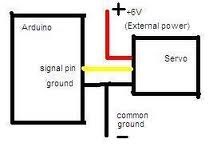
Oh, and listen to Rich... His suggestion is the way to go... Below is a diagram of how to add a 6V battery instead of using the EZB4 through put voltage to power the servo...
If anyone knows how much the EZ-B v4 can handle, i'd like to know.
That will depend on the thickness, width, length and material of the traces. As a total guess, based on the V4s size I would say it wont be much, 4 or 5 amps at best, possibly less.