How To Make A Wide Angle Ir Non Contact Bumper
I designed a wide angle IR (non contact) bumper for robots a while back but never used it. It may be useful to the folks here on the forum so I thought I would post it.
The neat thing about this IR bumper is that it will detect most objects in front of it without any scanning like using a rotating servo plus ranger so no moving parts and its very fast. It also reports back the position of smaller objects and also the rough width of close obstructions.
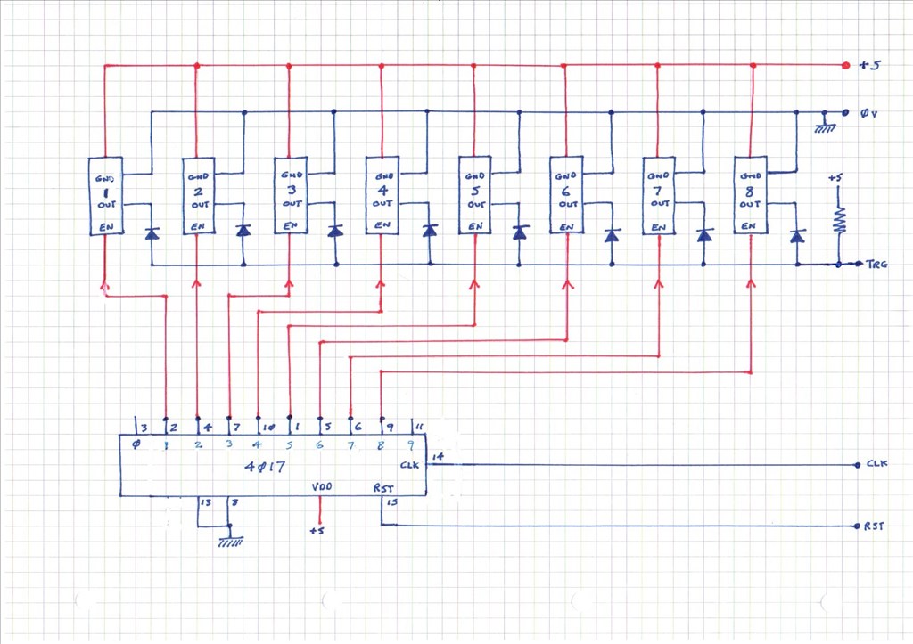
Here is the circuit diagram
It uses the Pololu 10 cm ranger modules https://www.pololu.com/product/1134
The forward detection range is 2 cm to 10 cm but its also possible to get another module that does 5 cm to 15 cm.
The design does not need to have 8 detectors (as shown) it would work with any number up to 9 but with lower numbers the detect gaps would get bigger. When building the cct you need to modify the IR modules so that the ENABLE line is broken out, this is detailed on the products web page.
The bumper requires 3 port lines on the EZB these are RST (output), CLK (output) and TRG (input)
How it works is first you reset the 4017 (decade counter) so the counter output = 0 which has no sensor attached.
Now clock one pulse on the CLK line and (only) sensor number one is enabled - now look at the TRG (trigger) line to see if it is low, if it is low then this sense zone has an obstruction.
Now clock one pulse and sensor number two is enabled - now look at the TRG (trigger) line to see if it is low (you may need a small delay of a couple of milliseconds here to get a steady output state), if it is low then this sense zone has an obstruction.
Repeat this until all sensors have been enabled in the line - you then have a crude picture of whats in front, where it is in the bumpers length and also how big (wide) it is horizontally.
With this bumper the robot can get a feel of the size of the object in its way - a small object in front of the bumper will show up as one or two detects a large object (say a wall) in front will show up as all 8 detects etc.
Disclaimer, I never got around to building this, but it is a pretty simple cct so it should work fine.
Hope someone finds this of use.
Tony

Thanks @Tony, I can see where this may come in handy installed in a Roomba when the external hardware extends beyond the physical front bumper sensors as well as extend the total object detection area.
@Robot-Doc, glad you like it, I think you are right it would be a nice add on to a Roomba.
Tony
This is very interesting. When I build my dog-bot I may do something like this. I currently have a "radar" type ping sensor on the front of my Roli, and although it keeps it from hitting walls dead on, it is not good at avoiding smaller objects or walls that only partially obstruct the path (like doorways). Something like this I think I could get wider coverage with better positional awareness.
Alan
Tony, I have found the 4017 very useful over the years for many different circuits. I will definitely keep this circuit of yours in mind when I get into finishing Questor's base platform. Thanks for the info. There are tons of useful circuits in my old Radio Shack Engineer's Notebook from 1980 by Forrest Mims. I still use circuits from this book to this very day. If anyone is interested I have the entire book saved to pdf and can email it to you.
Rex
Awesome idea Tony!
Actually the 4017 was one of the first chips I used in an electronics project. I used it for a cyclone eye circuit You know the ones where the LEDs light up to make the light look like it's bouncing back and forth, "Kit" from knight rider is another example.
The first chip I used was the venerable 555 timer, I built a servo tester with it Actually I think I used a 555 to drive the clock signal for the 4017 as well.
For those that want to build this sensor arrangement here is a jpeg of what my modded sharp sensors look like.
I modified them so that the LED can be seen from the front (not the back) of the sensor so you can see when they are detecting. This also shows the ENABLE pin being brought out.
Tip: use low current LEDs - the ones I use are very bright at only 3mA
Here is the same sensor used on the EZ:2 (type 2) claw.
Tony