Welcome to Synthiam!

The easiest way to program the most powerful robots. Use technologies by leading industry experts. ARC is a free-to-use robot programming software that makes servo automation, computer vision, autonomous navigation, and artificial intelligence easy.

Get Started
Asked — Edited

Home Base Finding Design Using A Ir Beacon Idea

Little while back someone made a post on home base finder ,and since it was so hard to find a good idea since there was many soloutions.

I decided to test one i found was very good thanks rgordon

First i put the circuit together and it worked very well

Second test is to use the arduino code to learn how it tracks


IR BEACON ROBOT TRACKING

3RD test is to convert the arduino code to EZB

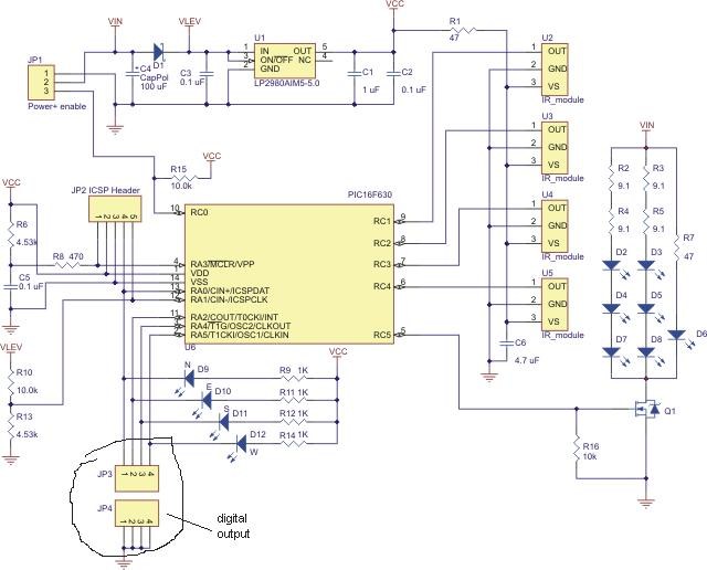
It uses 4 IR transmitter and receiver pairs ,like a compass
it updates 1000 times per second as said on the pololu website

Alot faster then any camera or some other designs can do

here is a link about how it works

pololu ir beacon transceiver

also you need a set of them, one on your robot and one on home base


pololu ir beacon transceiver pair

Also they work great in the dark,so no lighting is needed ,will have photos and data as i make it


ARC Pro

Upgrade to ARC Pro

Become a Synthiam ARC Pro subscriber to unleash the power of easy and powerful robot programming

United Kingdom
#7  
I clicked on the link, it took me to some armadildo project. Can't say I saw a schematic on there. The only schematic is this one

User-inserted image

Unless I'm missing something (which I may be, the schematic is not exactly high resolution) where does it say it's digital?
Edit: Seems you edited before I finished typing. Is that digital then? I understand JP being jumper or link, nothing specifically digital. I'm not disputing you I am just asking as I don't know.

And unless you don't plan on attaching any servos, motors, h-bridges, ultra sonic, MP3 board, switches etc. you're going to end up with less digital ports left over than analogue.
#8  
reason of accuracy is reduced it not about using digital or analog.
Analog is for measuring distance,this one is about tracking distance

LIKE the way the IROBOT ROOMBA beacon design is made ,but this adds more
ROOMBA beacon uses only 3 ir beacons 2 at angle and 1 in the middle
so you only getting about 90 deg about

ON pololu design it uses 4 IR beacons at 360 deg plus very fast updating 10000 per second

SO IT SEE FOWARD ,BACK AND SIDE TO SIDE and anything in between
#9  
TRY to understand the circuit ,me is easy
look at JP4 all connections are ground ,so if you jumper to JP3 will be grounded and leds with be always on

Also if you look at the circuit its only ouput
now this is a way to make your own circuit using IR MODULE like in the circuit without the nicroprocessor

And use EZB instead,it would need a PWM to analog CONVERTER, but that idea is way over most people head to design ,except for me

IR using one of our sharp IR sensors DJ sells,it can work too ,but may have a problem with interference

Some of my tech info i know its hard to understand unless you have a degree or something close to it

ALL i can do is try to explain it,so its easy to understand
#10  
maybe this is better to understand the design near the bottom says about digital outputs


The beacons work by transmitting and detecting infrared light, much like a television remote control. Each beacon has four IR emitters and four IR detectors. The beacons alternate between transmitting and receiving so that they never get confused by reflections of their own transmissions.

The transmit and detect cycle is carried out more than one thousand times per second, and a small microcontroller monitors all four detectors to decide the direction to the other beacon. The beacons have four red LEDs that indicate the direction to the other beacon; if you take two beacons and rotate them, the LEDs will always keep lighting up in the direction of the other beacon.

Interfacing to the beacon is simple - it has four digital outputs that indicate which of its four sides detects the other beacon the strongest. You can establish the direction to another beacon to within a few degrees by rotating the beacon back and forth and noting the point where the output switches from one side to another. An enable input lets you select between active mode and a low-power mode.
#11  
here is the arduino code that needs to converted to work with EZB


#include <Servo.h>
#include <AFMotor.h>
#define TOPSPEED 200

// servo SCANNING VARIABLES //
Servo myservo; // create servo object to control a servo
int servoPosition = 0; // variable to store the servo position
const int SERVO_PIN = 10;
int floorState = 0;
long frontReading = 0;
boolean scanIncrement = true; //increase position?
byte servoIncrementValue = 6;
byte servoDecrementValue = 6;

// MOTOR VARIABLES //
AF_DCMotor rightMotor(4, MOTOR12_8KHZ);
AF_DCMotor leftMotor(3, MOTOR12_8KHZ);

// TRANSCEIVER VARIABLES //
int notFoundSensitivity = 500;
int west = 0;
int south = 0;
int east = 0;
int north = 0;
int dir = 0;
boolean detected = false;

// TRANSCEIVER DIRECTION MODE VARIABLES //
const int NUM_READINGS = 10;
int directionReadings[NUM_READINGS];
int modeOfDirections = 1;
int index = 0;

void setup()
{
Serial.begin(38400);
myservo.attach(SERVO_PIN); // attaches the servo on pin 9 to the servo object
myservo.write(0);
rightMotor.setSpeed(200);
leftMotor.setSpeed(200);
delay(1500);
}
Ireland
#12  
@robotmaker
You may be correct that its digital
My reference to adc ports is because I use them to monitor the outputs from the IR Beacon at present and it works very well .

Please may I move the post forward
@Rich is concerned about using up to 4 ports (digital or Adc)
my proposal is to try to limit it to one ADC
I am simply putting the idea forward
If we were to add a potential divider to all the outputs ( using a different value resistor in all 4 circuits ) could we then use one ADC to identify which ir N,S,E,W is active


e.g
1 volt on adc0 North
2 volt on adc0 South
3 volt on adc0 East
4 volt on adc0 West
United Kingdom
#13  
That would work, and solve the problem of using 4 ports. It would need to be done on the ADC rather than digital though, but that's no issue from @Bravia's experience.

I assume on the ADC port it is either low of 0v and high of 5v or vice versa?
Ireland
#14  
I have used 4 adc ports to monitor ir beacon it works

@Rich
on the adc (ez-b ) it monitors any voltage between 0 and 5v ,as i listed in previous post

I will test the idea,or if someone can suggest a specific component I would appreciate

would a 4 input D to A converter meet our requirements *confused*
Ireland
#15  
@robotmaker
I note from your posts that you are an expert in circuit design
Would appreciate very much ,when you have the time to upload a schematic of a circuit to monitor the 4 outputs and produce a corrosponding voltage that could be monitored by the EZ-B adc port

Pat
#16  
WOULD have to be tested to see if it will work,on idea might look good but testing is always better

And not shore is it will update as fast at 100000 per second
on digital is aways faster then anolog ,main reason analog first reads ther valule and then converted to digital

SO using digital the conversion is direct and faster

there is a simple circuit to use only only 2 digital ports with 4 digitals using gates

AND after me reading my info again on A-D conversions its not faster
#17  
its a simple voltage divider using 5 resistors at the same value,really the best circuit to use is D-A but like in my last post it wont be very fast updating ,thats what you really wont

TO make a D-A CIRCUIT will take a lot of parts,and each time a circuit is added to another circuit it slows it down.

I GUESS really need to read up on a A-D on how it works and design and the speed to fully understand it.

on D-A conversion is a voltage string depending on the bits and then a comparator for each bit and then a digital cicuit to convert it
Ireland
#18  
@Robotmaker
would the ic in link be suitable eventhough its an 8 bit input
http://www.ti.com/lit/ds/symlink/dac0800.pdf

If one is not into schematics please you dont need to understand this is all in a single component
and the cost is only a few $ or £ or ?
#19  
yes it will work,only will have less speed,and thats what you really need,it will be super slow,because of first goes to first D-A and then second A-D on ezb and all the conversion is done on both.

thinking you use ezb Analog will give about 2500 per second and then need to divide another by 4 again is 625 updates per second ,on the digital you get 10000 updates per second

Only reason that you want a very fast updating is because you want the robot to turn left or right to stay on track to the home base finder or it would wonder all over the place

IT same about using a camera to find GLYPH you need it very fast to update the servos

I DONT thing the camera can update as fast at 10000 updates per second
Ireland
#20  
Thanks for that
will test circuit like I said and willl post results
Pat
#21  
DO you have a scope to test for the cycle updating speed

in that circuit you need a good reference circuit and op amp to convert non inverting and inverting inputs to analog output

look near the end of the pdf file you put up
#22  
RICH i think you click on the first link ,its the one that says POLOLU IR BEACON TRANCEIVER
its the second link third one is pololu ir beacon tranceiver pair
#23  
@BRAVIA read this its current output not voltage output

The DAC0800 series are monolithic 8-bit high-speed 2. Fast Settling Output Current: 100 ns
current-output digital-to-analog converters.

i and i didnt see it was that slow i thought it would be much higher ,might be cause it 8 bits or type of design 100ns witch is 100 nano per second
#24  
HERE is a site i use alot for very good info on docking logic ,finding home base and charging
it alot of different ideas

docking logic

there are over 50 pages just to let you know,i did print all of it about 5 years ago

When i was really into the finding home base designs and testing all types


IR DOCKING DESIGNS

GO TO CHAPTER 3 on IR docking it talks about why a omnicone is so very important
#25  
I ordered the parts to make my own IR BEACON like the pololu design ,but using EZB as the processor

Also the cost is about $15 ,and may need 5 digital I/O PORTS ,but also ordered a chip to use I2C buss and have a extra 8 digital I/O inputs ,chip is under $1
#26  
I got a few parts in and waiting on my IR detectors from mouser,and my clear acrylic tube to make it nice and pretty like sensor.you dont need the acrylic tube to make it work

Since the pololu IR BEACON design doesnt have it
most likeky wont get it done before i leave friday on my long work trip
but will be able to run tests on the pololu IR design to collect data,pwm and timming and more.