robotmaker
Little while back someone made a post on home base finder ,and since it was so hard to find a good idea since there was many soloutions.
I decided to test one i found was very good thanks rgordon
First i put the circuit together and it worked very well
Second test is to use the arduino code to learn how it tracks
3RD test is to convert the arduino code to EZB
It uses 4 IR transmitter and receiver pairs ,like a compass it updates 1000 times per second as said on the pololu website
Alot faster then any camera or some other designs can do
here is a link about how it works
also you need a set of them, one on your robot and one on home base
pololu ir beacon transceiver pair
Also they work great in the dark,so no lighting is needed ,will have photos and data as i make it

@robotmaker Just setup pololu beacon pair also interfacing to EZ-B requires very little programming it has four outputs once it is in sight of transmitter one is low all other three are high depending on its position connect to ADC port and off you go
That should be a piece of cake to script then, just needs to know when it's in the line of sight of the beacon (IF statement or ADC_Wait) and then rotate the right way until front and centre is in line with the beacon (IF statement to work out the direction, ADC_Wait to turn until lined up).
If only it didn't need 4 ADC ports.
it uses 4 digital ports not analog ports RICH and BRAVIA,it has a h and L output
DO i always have to correct you RICH LOL
@Rich very important point ( 4 ADC Ports ) with so much sensing required for project why not use a digtal converter and one adc port on EZ-B
or keep it simple We have 4 outputs ,place a resistor of different value on three outputs that would give a specific voltage that would identify each one
What is it, Digital ports or Analogue ports? Receiving conflicting information here...
4 Digital ports is worse still!.. The digital ports are usually a higher premium than the ADC.
I guess if it just goes either 0 or 255 (if ADC, which I guess is 0 and 1 on digital if you want to get technical) then the bumper switch circuit I knocked up a schematic for a few weeks back would be useful. But, if it ranges from 0 to 255 depending on how close to centre it is then accuracy is decreased (and if used digitally accuracy is drastically reduced as anything over 0 is on and 0 is off)
ANALOG ports we only have 8 ON DIGITAL PORTS IT 20
I guess nobody looks at schematics on the link i gave
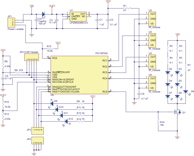
@BRAVIA check the link on pololu tranceiver ,the schematic is near the bottom ,it has N ,S,E W with leds on each output and the output is digital NOT analog
i know my artwork i did is bad,dont laugh
I clicked on the link, it took me to some armadildo project. Can't say I saw a schematic on there. The only schematic is this one

Unless I'm missing something (which I may be, the schematic is not exactly high resolution) where does it say it's digital? Edit: Seems you edited before I finished typing. Is that digital then? I understand JP being jumper or link, nothing specifically digital. I'm not disputing you I am just asking as I don't know.And unless you don't plan on attaching any servos, motors, h-bridges, ultra sonic, MP3 board, switches etc. you're going to end up with less digital ports left over than analogue.
reason of accuracy is reduced it not about using digital or analog. Analog is for measuring distance,this one is about tracking distance
LIKE the way the IROBOT ROOMBA beacon design is made ,but this adds more ROOMBA beacon uses only 3 ir beacons 2 at angle and 1 in the middle so you only getting about 90 deg about
ON pololu design it uses 4 IR beacons at 360 deg plus very fast updating 10000 per second
SO IT SEE FOWARD ,BACK AND SIDE TO SIDE and anything in between