
DaMan
Canada
Asked
— Edited
H-Bridge Without Vcc
Hey all,
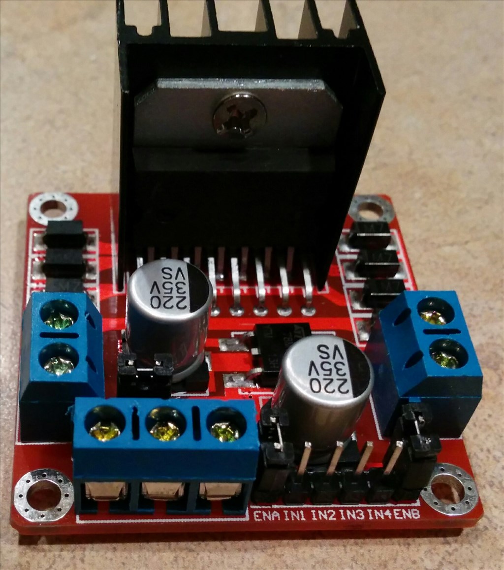
I've been out of the ez-community for quite a while but I finally ordered and just received my long awaited h-bridge(s). Unfortunately mine seems to be quite different. Instead of VCC, mine says 12v. Before I blow up my EZ-B, can I assume these are the same connections?
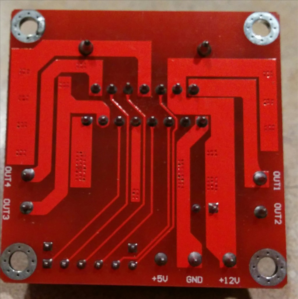
Also, as you see in the attached photos, my pins are located differently from the others I've seen in my search results on the forum. Which enA and enB pins do I use? Front or back? Or just trial and error?
Thanks! -DaMan

I'd say +12V is the VM/Vcc/Vs (the voltage that goes to the motors).
Ena and Enb use the front pins if you remove the jumpers, or leave the jumpers on if you don't need PWM control.
Follow the traces on the board. Look on the L298 datasheet (it's on my google drive datasheet repository) and see what the pin is. Pin 4 is supply voltage (50v max), 9 is logic supply voltage (7v max). Pins 6 & 11 are ena and enb.
Great thanks Rich... I've learned a lot from your tutorial, I just didn't want to make a mistake assuming the 12v was VCC. Following the traces made sense.
Also, I really like your idea of the y-cable for the enA and enB. ON this board it's mush easier than soldering the 2 together.
However I'm a bit confused. If I solder the enA and enB together will I still get PWM? or does each require a signal cable to supply independent PWM control?
Reason being, I don't know if each DC motor runs the same speed and since my robot uses tracks, I need to be sure one track doesn't spin faster than the other. Sorry if this is obvious on your tutorial. I think it's just a bit over my head lol
Thanks again.
If you leave the jumpers on the ena and enb will both be at +5v which is full speed with no control over it.
If you made a Y cable for the PWM and connected it to the ena and enb then you would have PWM control over the speed but one control for both motors - i.e. both would run at the same speed percentage. If one motor is slightly faster than the other then this wouldn't help, changing the PWM would make both motors spin slower but the one would still be slightly faster than the other.
If you connect each ena and enb by theirselves, so taking up 2 digital ports (i.e. D18 to ena and D19 to enb) you can change each motors speed independently, you could for instance have motor 1 spinning at 25% speed and motor 2 spinning at 75% speed.
Personally I prefer to use 2 separate PWMs for the motors, one each, giving that independent control.
Hopefully that made sense.
Perfect thank you... I Am soldering as we speak so I'll update on how things go!
Thanks yet again! -DaMan