
JS1
H-Bridge Question
I'm a newbie when it comes to electronics, so perhaps (definitely) a stupid question here .. I have installed the 2.5 motor controller/H-bridge with speed control. Added the PWM controller in the project and can modify PWM between 0 and 100.
Now the question .. when setting PWM to 100, will the + and - going to the DC motor be exactly the same as when connecting the motor directly to the 7.2V battery ?
The reason I ask is that when I connect the motor to the battery directly, it runs, when when I connect it to the motor controller with PWM=100 it doesn't run (I set also the forward/reserve digital signal). I have an amp meter from my father (which I don't understand really how it works ), but I see the needle swinging to the right when connecting it to the motor controller (exactly the same as connecting it to the battery). Setting PWM=50, the needle swings half way as I would expect.
Thanks and regards Johan

Yes, 100 would be the same as full on. I suggest reading Rich's excellent H-bridge tutorial here (it is probably something simple, like the little switch in the wrong position):
https://synthiam.com/Community/Questions/4096
Alan
Thx Alan
I followed Rich's manual to the letter. Using the EZB4 with H-bridge and speed control. Pressed the white button so the red light switches on. Is the motor controller sending 5vdc to the engine at PWM=100 ? If so, that might be not enough and I need to hook up another external battery to the H-bridge like discussed here : https://synthiam.com/Community/Questions/5703&page=2
Thx for yr help Johan
It will send whatever voltage you provide to the Hbridge. If you are connecting your EZ-B v4 to your 7.2v battery and connecting the power from the EZ-B, it will get 7.2 volts. If you are using a v3 EZ-B, then you will want to just have signal and ground from the EZ-B and power and ground from the battery to the H-bridge because a v3 EZ-B will regulate the voltage down to 5v
Alan
The Vcc and Ground on the 3 terminals on the bottom (labelled Vcc, Ground, 5v) are what effectively go to the motors connected to Out 1, Out 2, Out 3 and Out 4.
For instance, if you supply Vcc with 7.2v directly from the battery and it's ground then, provided the correct logic is applied to the In1, In2, In3, In4, EnA and EnB, this is what your motors will get.
EnA and EnB use the PWM to vary the voltage on Out 1 to Out 4. If EnA for instance is set to a PWM of 50 in ARC it will apply half of Vcc to Out 1 and Out 2 (depending on the logic of In1 and In2), in yout case 7.2 / 2 = 3.6v. If set to 75 it will apply 75% etc.
If it's not working then it's most likely that you have not set the PWM or the logic of In1 to In4 is incorrect. You must always set the PWM on EnA and EnB to something before attempting to move a motor otherwise it will act as if EnA and EnB receive a low signal or PWM of 0 even if it is a high signal.
An init script to set PWM to 100, or in some cases it may be better to set to 99 then sleep for 100ms then set to 100 may help.
Where it's assumed D0 is EnA and D1 is EnB
Many thanks for your help
I think everything is as it should. My setup
NiMH accupack 7.2 V 4600 mAh I only have one DC engine (Voltage unknown) EZB4 H-Bridge
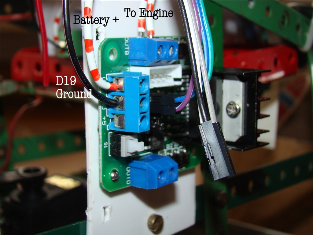
H-bridge connections: D19 signal (white) to ENA (for speed control) Plus battery to VCC D19 ground (black) to GND Nothing connected to H-bridge 5V D15 signal (white) to IN1 D16 signal (white) to IN2 ENB, IN3, IN4 not connected OUT1/OUT2 will go the the engine
here the three signal cables:
The connections of D19, D15, D16 at the EZB4
On boeard regulators are active (pressing the small button) All the scripts are in place. I also tried the following
PWM(D19,99) Sleep(100) PWM(D19,100)
Now the strange thing. Here I show the Voltage (?) output from the H-bridge to the engine when PWM=100. I would have expected 7.2V, but perhaps the device is not working correctly.
Here I show the Voltage (?) output from the H-bridge to the engine when PWM=0. Nothing is shown; When I use PWM=50, the needle goes in the half position.
Here is the Voltage measured at the output of the battery (it is the same as the output of the H-bridge when PWM:=100)
So I would have expected it should work, but it does not. When I connect the motor directly to the battery, it runs. When I connect the motor to the output of the H-bridge is does not run.
I'm completely in the dark ...
kind regards Johan
just to note that on the photo of the " connections of D19, D15, D16 at the EZB4", there are two pins free between the green and purple cable. On the photo it seems three pins.
js1
the little whit button chould be puched in.
Hi nomad,
yes it is switched on and the red light shows. If I don't push it, no output goes to the motor I noticed