
Mulberry
USA
Asked
— Edited
H Bridge Wiring
Evening All
So I'm working on wiring my H bridges that I purchased through E-Z Robot. I was following the tutorial describing the steps (see below) but soon realized my H Bridge is slightly different from the one in the demo. In fact, the wiring diagram (photo on the page) is different from completed version in the video.
https://synthiam.com/Tutorials/Hardware.aspx?id=25
Is the video simply out of date, and if so, should I follow the wiring photo?
Thanks,
Daniel

Don't really know what you have there. Can you send a good picture?
You should have one input where you supply the power needed to run the electronics on the board. This should be labeled 5v (or something like that). You should attach this to the center pin of one of the Digital ports.
You will have one input where you supply the power needed to run the motors. This should be labeled VCC (or something like that). If your only supplying 5vdc to motors you should attach this to the center pin of one of a Digital ports. If you are supplying more then 5vdc or up to 40vdc you can attach this to an external power supply.
There will also be an input where you attach a ground. If using an external power supply make sure you make this a common ground between that supply and the EZB.
Then you will have one or more outputs that will supply forward or reverse voltage to the motor(s). Hook up the two wires coming from the motors here. Tip: Don't attach a motor till to know you have it wired up properly and are getting the expected out voltages in both forward and reverse. Use a multi meter. on the outputs. Only when you get the expected voltages then should you attach your motors. This will save you a lot of head and heartaches.
Now you will have two control wires for each motor. one for forward and the other for reverse. Don't know how your board is marked but if it's marked like the pic you linked to then wire it up like that. Example: IN1 to an outside pin (signal) of a digital port.
Tip: if your running two motors and don't want them to move in tandem, do not jump the pins together like DJ shows. Leave the jumper out between the pins and install two PWM controls instead of one. One for each motor. That way you can run each motor at different speeds and independent of each other.
Tip: You must have a PWM control installed and turned up to at least 20% in ARC to get your H-bridge to work.
Good luck, Dave Schulpius
If you check my Jarvis showcase I have posted some photos of the wiring to the H-Bridge (post 63). I have also added a H-Bridge setup to the cloud to make it easier to set up.
As Dave has said, you must make sure you have PWM control added and turned up (or use Set digital and set to on) if you have used the 5th wire. You can supply 5V to the PWM pins but will lose speed control.
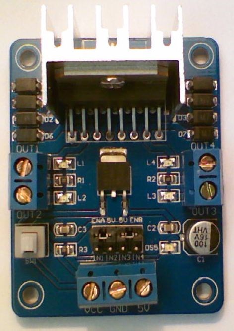
Setting Up L298n H-Bridge
Assuming ports D15, D16, D17, D18 & D19 D15 Signal > Left Trigger A (In 1) D16 Signal > Left Trigger B (In 2) D17 Signal > Right Trigger A (In 3) D18 Signal > Right Trigger B (In 4)
D19 VCC > H-Bridge 5V D19 Ground > H-Bridge Ground D19 Signal > H-Bridge ENA & ENB
D19 Signal will need to be connected to 2 pins on the H-Bridge and the jumpers on the H-Bridge removed. I made a Y cable out of a couple of jumper cables.
Connect the positive of the battery to the H-Bridge VCC
Connect motor 1 to the Out 1 and Out 2 terminals Connect motor 2 to the Out 3 and Out 4 terminals
In ARC add a 4 Wire H-Bridge control and a PWM control.
Set up the H-Bridge control as the above D15 to D18 on LTA, LTB, RTA and RTB Set up the PWM control to D19
To use, set the PWM to 100% (or a lower value if you want it slower) - I have mine set to 100% in an init script that is run on successful connection of the EZ-B. Use the H-Bridge control and the motors should move.
Here is a project with both controls added, you can save it and merge it with your project (or open it and test the H-Bridge). It's also accessible in ARC by opening from the cloud.
Note: The PWM wire is optional. If you wanted to save a digital port and lose speed control you could connect any of D15 to D18's VCC to the H-Bridge 5V and any of the D15 to D18's Ground to the H-Bridge Ground. Keep the jumpers on between ENA and 5v and ENB and 5v.
If your H-Bridge looks different, they are pretty much all much of a muchness. A H-Bridge generally has 4 inputs to control the 2 motors plus 1 or 2 inputs for speed control. The same principal as above can be applied.
Signal wires from Digital ports to each of the inputs to control the motors. Generally labeled In1 to In4 or AIn1, AIn2, BIn1 and BIn2. Signal wires (this can be combined for 1 port if you don't want individual speed control from side to side) for the PWM or speed. Generally labelled as ENa and ENb. +5V or VIn is generally the 5V from the EZ-B Vm is generally the supply to the motors taken from the battery. Ground is always Ground, taken from any ground since it's a common ground.
A simple truth table for how the H-Bridge works.
So to use that on the robot, setting digital to on (1) and off (0) as follows
If the above doesn't help you please post a photo of the H-Bridge or list it's connections.
Great. You both were a huge help. I believe I understand. The bridge used in the tutorial was slightly different.
Thanks again!
Daniel
Holy Cow Rich. where were you when I was trying to figure this all out? Nicely done!
That's what happens when I have nothing to do but wait around, I had an unexpected wait for about an hour today so edited it and, well that's what come out