Norway
Asked — Edited

Ez-Bv4 To Control Underwater Rov?

Hi. I am curious if the EZ-Robot hardware and software might be a good solution as a control system for my underwater ROV that I am building.

Although I have tried to create something using arduino myself, the programming is really a steep learning curve for me.

I will be running a wired Ethernet connection from the surface and have a wifi hot spot in the rov to allow connection to the bv4. It must control 9 brushless esc's. 6 for movement (thrusters) and 3 for a robotic arm. Also one servo for moving the camera vertically. The esc's use the same signal as servo's do, so I don't think this will be a problem.

I will also need to control 3 relays.

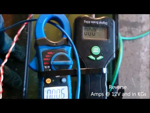
I have this unit for sensing battery voltage and current draw: https://www.coolcomponents.co.uk/attopilot-voltage-and-current-sense-breakout-180a.html This can be connected to the ADC pins correct? This is made for 3.3volts, but can it still be used maybe?

I have this IMU from OpenROV that I want to use:
http://store.openrov.com/collections/frontpage/products/openrov-imu-depth-module

I see there already is support for the MPU-9150 chip. But is it possible to also get the depth and temperature rating from the MS5803-14BA chip?

I want all to be controlled with a gamepad/joystick. This means that multiple motors must react differently to stick movements. For instance, if I want the ROV to turn in place. 2 motors must turn clockwise and two counterclockwise.

Would all this be possible to do?

Br Ole


ARC Pro

Upgrade to ARC Pro

Join the ARC Pro community and gain access to a wealth of resources and support, ensuring your robot's success.

#1  

It will take some scriping, but nothing seems like it can't be be done.

Alan

#2  

Hello,

Alan is right. I would think all propulsion motors could be controlled. My only question is, can the signal get from the pc, or joystick device to the ROV through the water. Otherwise a remote antenna may be needed?

It would be real COOL to run the camera to scan as it runs..

Ron

#3  

@Andy Roid.... If you read his post he states he is going to have a wifi hotspot on board the rov itself....

#4  

Hi Richard,

I did and understand, but depending on depth, and distance, would the signal be maintained? Otherwise it may need a teathered antenna? I don't know. I have very limited experience with Wifi through water. I just want to mention it.

This sounds like a real nice project. Can't wait to hear more.

Curious .. Would a Ping sensor work?, (in water), to determine depth below the ROV.

Ron

#5  

I will run a wired network down to the ROV. Standard Wifi signals only travel a few inches under water.

How does "some scripting" compare to programming all the functions on an arduino board? Much easier I expect.

Also, is there any way to embed my two IP cameras in the control software using the "ONVIF" standard? The http feeds they give are laggy, some times up to a few seconds. But using ONVIF software to view the feed there is no delay.

If not, I can treat the video feed and control system separately.

I will try to draw up a what I am thinking during this weekend to make it a little easier to understand what I want to do :)

#6  

EZ Robot just came out with a low cost ($169.00 usd) robot called Adventure Bot. Most of the basic devices you want to work with are on this unit. The EZB v4 and camera can transfer to your ROV. The wheel servos can mimic the propulsion motors. Camera position can be set up with an additional servo which you may already have. Take a look and see if it meets your needs. I am not a salesman for EZ Robot, LOL, but I REALLY enjoy my EZ Robot kits. This would give you an opportunity to see how, with learning from the tutorials, easy the EZB software is to use. I believe this may be a way to go.

The EZB v4 is software expandable not a limited controller. You will see it should fit your ROV needs.

Good Luck and have fun..

Ron

#7  

Scripting is much simpler that programing an Arduino. You'll be able to use a combination of built in functions and scripts. The most difficult will be the depth sensor. I2C can be tricky to get working. I think the voltage / current sensor will work out if the box, but EZ-B has built in voltage sensor as well.

Can you send a link to the ESCs? Some things that claim to work "just like servos" don't. If they arw inexpensive enough, I would be happy to buy and test one before you make an EZ-B investment. (if you were in the US I would loan you an EZ-B to test with, but shipping back and forth to Norway would be prohibitively expensive).

Alan

#8  

@olegodo

Hello,

New prices on EZB products. Check them out when you can. Any updates on your project?

Ron

#9  

Hi again.

Thanks for all the replies! This seems promising! The recent price drop is also welcome;) I have been working on this ROV for quite some time now and most of the hardware parts I already have. I have also designed a 3D printable thruster that I will use. Tests of it can be seen here:

And using the same motors, I have made a 3D printable linear actuator design I hope to be able to use in the manipulator arm.

In order to give you a better overview of what will go in to this project, I made a diagram showing all the electrical components I plan on connecting. Note that all the components marked with "*" is stuff I already have.

User-inserted image

If you have questions or comments, please let me hear them. Does this still look like a good job for the EZ-B4?

Regards Ole

#10  

I think EZ-B will be a perfect solution for this. Is your tether going to be strong enough that you ca use it for fail-safe recovery or are you going to have a way to drip ballast or inflate bladders or something in the case if a connection loss? Although highly reliable, I like to think about what could go wrong. When working underwater, recovery becomes a significant concern.

Alan

#11  

Can you post more information about your 3d printed linear actuator and the clutch system? I love the design and am looking for linear actuator ideas on my astromech :)

Thanks Aaron

#12  

@thetechguru

The tether will be strong enough to pull the Rov and lift it out of the water. Also, the Rov will be slightly positively buoyant. So that if all fails it will slowly float to the surface. This also means that the vertical thrusters must spin constantly in order to keep it from floating up. This way of doing it is quite standard on the smaller rov's and the extreme depth type. Some sort of "hold depth" would be nice to have if possible to implement in the software.

@robot56 At the moment I have only made a proof of concept prototype. It's made to fit the magnets and threaded rod I already had. But I have no problem sharing what I already have and the finished design later on.

About the control of the ESC's. They operate on a PWM signal between 1000 and 2000 pulses pr second I believe. 1000 is full reverse, 1500 is natural and 2000 is full forward. This is the same signal type that the EZ-B4 sends to the servos right?

#13  

I see in the BV4 datasheet that you can supply it with a maximum of 16 vollts. (I know the D0-D23 pins are unregulated) Does this mean the board will blow up if I supply it with 16.8 volts max? The reason is that I am using a 4s lipo battery pack witch at a 100% charge has 16.8 volts. If I could use this directly I could use the built in voltage sensor to see my battery voltage instead of finding some other way of doing it.

Ole.

#14  

Sorry to bump this thread. But can anyone comment on my last post about the battery voltage?

PRO
Canada
#15  

No, the board will not blow up, but it may run a little hotter than usual. That being said, I haven't done any prolonged testing at that voltage (I've only tested for an hour or 2) so there's no guarantees for prolonged usage above 16V.

#16  

I see. Thank you for the reply! My v4 is on its way now and I am looking forward to playing with it :D

#17  

So just a suggestion but why not use a DC to DC converter to power just the ezb, drop that 16.8v down to a manageable 14.8v I have them avail if you need one at a reasonable cost.

#18  

Yes, I could do that. But I was hoping I could use the internal voltage sensor to tell me the voltage of the batteries without having to add more hardware.

#19  

The ez-b has a voltage sensor. It can be accessed through ARCs v4 info panel control. Not sure what it is called exactly.

I like the principles of this. Though, one point is anything that gets plugged into the ez-bs digital pins will be getting 16.8v. You must regulate the ez-b or the assesories down to the voltage they need. Regulating the ez-b needs a high amperage regulator running at a voltage the attached modules need. If you regulate each module(in the event they use different voltages) you need to regulate the power from the ez-b before it hits the module. Regulators can be bought in the store, or you can buy regulators from eBay or some other source.

#20  

I have tested my brushless esc's with my ez-b now and they work nicely :D

However I am having some troubles with my relays. It turns on, but not off again, to make it turn off I have to reboot the ez-b. I have measured the signal pin on the ez-b to rule out that there is a problem with the relay itself. I also tried different ports. I have tried using the "set digital" control and buttons on my gamepad. The scripts I have tried using on the gamepad buttons are:

"Set (D0,ON)" "Set (D0,OFF)" "ToggleDigital (D0)"

Am I doing something wrong? confused

PRO
Synthiam
#21  

Can you ensure that you haven't also used that port since last power on for servo or PWM? Because if you used the port for something else, it will not be happy to be used for two things at once unless that's what you want to do.

Check to ensure nothing else is using port D0

#22  

Someone else was having this issue recently. I think they solved it with a pull-up resistor or capacitor. I can't find the thread, but I haven't searched too hard either (answering from my phone).

Alan

United Kingdom
#23  

@olegodo.

I think Alan was referring to my thread as I had a very similar issue. There are different kinds of relays like latching and toggle ones (which sounds like what you need), and the one I was using had the same problems as what you're having.

Richard R very kindly linked to a relay brick that is fairly cheap, and is simple plug 'n' play with a 5v regulator to a digital port, and this relay works really well using SET(D0, ON and SET(D0, OFF commands.

Hope that helps.

#24  

Yup, that is the thread. My memory is shot this week. Didn't remember that I had participated in that thread.

Alan

#25  

Thanks a lot for the response. I read your thread @Steve G , and I have the exact same relay that you had problems with. Should have been able to find this if I only did a search in the forums I guess eyeroll

So, either buy new relays or use a logic converter right? Or might it be possible to get it to work using a pull down resistor on the signal pin?

#26  

Got the logic converters today and they did the trick. I can now switch on and off my relays! :)

More questions though.

I have it set up so that button one on my game pad executes "Set(D20,ON)" and button two is "Set(D20,OFF)" This works fine. But from what i read the "ToggleDigital" command should do the same job with only one button right? Pressing it once should turn the relay on D20 on, and pressing the button again should turn it off? I tried this and it seems to work some times but not reliably. Maybe I need to add something more to the script for the button to make this work? Aslo, perhaps it is possible to have one button turn on/off multiple relays one after the other? For instance. First button press turns on relay 1. Second press switches relay 1 off and turns on relay 2. Third press turns off both off. Press the button a fourth time and the cycle starts over.

If anyone can point me in the right direction for doing this it would me much appreciated!

BR Ole.

#27  

I would script that using a variable to keep track of the current status and taje the action based on the contents of the variable.

Let me know if that isn't enough to get you on the right track and I'll write upba sample script.

Alan

#28  

When I setup relays I used a tip 120 which opened to ground to close the loop to the relay , this always worked

#29  

@thetechguru thanks for the pointer. I will try to look in to using variables for this.

@jstarne1 not quite sure what you mean. "tip 120"?

For the toggle command. could it be that I need to ad some delay for it? Or a way to ensure that it only toggles once per button press?

#30  

A tip120 is a common transistor. Used to provide a higher voltage switch from a low voltage signal (depending on voltage can be used instead of a relay, or as @jstarne1 pointed out, can be used as a cheap logic level converter to a relay. Here is a tutorial thread on their use: https://synthiam.com/Community/Questions/3050

Not sure about toggle command. I haven't used it much.

Alan

#31  

Okey. After spending more time on the hardware side I am now tinkering with using the EZb to control everything. More specific the thrusters.

I want to use what is called a vectored thrust setup. As you can see in the far right example in the picture below, this setup uses one motor/thruster in each corner of the craft. All on the horizontal plane, but at an angle. What this allows is for greater maneuverability in all directions on the horizontal plane and more or less equal power in all directions.

User-inserted image

I have tried to set this up on my test bench now using the joystick module, a 360 controller and Multi servo for each axis. I have set up so that the left stick on the controller moves the craft (spins the motors correctly on my test bench) forward when I push the stick forward (Y axis) And pushes the craft left and right along the X axis when I move the left joystic in the X axis. Good stuff.. simple. But I then want to turn the craft left and right with the right stick. (X axis on "Joystic #2") This is easy to do on its own. same way as I already did with the other stick, only reverse two of the motors and the craft would turn around its own axis. My problem is that I also need to turn it while moving forwards, backwards or sideways. This doesn't seem to work properly with this approach.

If I'm moving forward and then turn using the right stick, all motors starts to respond to the right stick and ignore the command from the left. So the craft would stop moving forward and then turn.

Does anyone have any idea if it is possible to make this work in some way? All suggestions are more then welcome! And I am aware that all off this might be impossible to understand only by reading this, so if you don't get it, let me know and I will try to explain better.

#33  

After some more thinking, this is actually just the same as a normal tracked robot. I can treat it the same way, but I need to be able to turn left or right gradually while moving forward or backwards. This can't be too difficult right? I have looked at the roli code and searched a bit for something like this, but haven't found anything that does this yet.

Any suggestions?

#34  

If turning while moving is the goal why not just use a rudder?

#35  

A rudder will not work as the craft also needs to be able to move sideways. Instead of a rudder you could have the thrusters turn like a rudder, but that approach would complicate things a lot.

This video shows this type of propulsion in use.

#36  

I see. What thruster configuration did you decide to go with?

#37  

Nothing is fully decided yet but the "five thruster version" form the picture above is what I really wish to have and what my current frame is designed to use. This is also what the ROV in the youtube clip is using.

#38  

Quick question. What is teh EZ-Script equivalent command for arduinos "map" command?

For instance if I want to take the joysticks -1 to 1 range and map it to 0-180 servo pos in a custom script?

#39  

Er du her fremdeler Ole? Jeg er i ferd med å starte et prosjekt og lurer på om det er EZ-B eller Arduino jeg bør satse på, og hører gjerne fra deg hvis du har lyst til å dele erfaringer / løse problemer :)

Claus (Hadeland)

PRO
Synthiam
#40  

Use multiplication :)

-or-

easier, assign the joystick to use a Virtual servo (v0-v99). And in code, simply get the virtual servo value. That way you can let the joystick control servo handle the range.


$x = GetServo(v2)

User-inserted image

#41  

Back when I tried to get this to work I had a hard time figuring out how to do it. I knew it had to be something along the lines of what DJ just posted but I didn't get it working at the time. Because of "real life issues" of buying a new home and moving I put the whole project on hold and during that time I bought a different control solution that is made for ROV use. That system will go in my ROV and my Ez-b is now the heart of my recently built, fully automatic tennisball launcher for my dog. Way overkill to use the ez-b for that. But since I already had it and it so easy to setup I figured why the hell not. Will post pictures and video of that thing later at some point.

PRO
Synthiam
#42  

Looking forward to seeing the pictures :D. Congrats on the new home!

Glad my explanation helped! Simply set any servos for virtual, and you can receive their values in code. Just remember, if you use the same virtual servo in more than one place it will be overwritten.