Asked — Edited

Automatic Battery Charger Docking

Anyone made a robot that finds its own charger and docks with it? What would be a good way to do this?


ARC Pro

Upgrade to ARC Pro

Take control of your robot's destiny by subscribing to Synthiam ARC Pro, and watch it evolve into a versatile and responsive machine.

United Kingdom
#1  

This is something on my to-do list but so far all I have are a few ideas...

Charging base with QR code on for identification. Script for when battery low it will search for the QR code and make it's way to the charging station.

Charging station will help guide the robot in to position to connect the barrel jack to the socket, have thought about putting a row of wheels down both sides of a channel which slowly narrows which will line the robot up perfectly with the plug/socket.

When fully charged bot moves out by itself and goes back to roaming mode.

Just a few scripts to do this, a voltage sensor script to monitor the voltage for low level and for fully charged and one to find the charging station. I have the low level monitor script written (I think it's on the cloud and in the scripts forum) but haven't done anything about the station or finding it.

Another idea I had was to have the base station have two bare electrical contacts and the same on the robot so when it drives in they connect up and it powers the charger but having bare electrical connections isn't too safe an idea.

#3  

Actually, the bare contacts isn't such a bad idea if there was something else on the robot that could act as a key to activate the contacts. You could get a bit creative with it if you combined the channel idea with the bare terminals:

One side of the channel is the negative terminal, the other is the positive...as the bot travels up the channel, it lines up and makes contact at the same time. When it gets to the end, some portion of the 'bot (be it an appendage or some unique feature) lines up with the base to activate a switch and opens the current.

You would have similar negative and positive plates on the 'bot that are activated via the same appendage once it met with resistance on the base.

Just a thought. :)

United Kingdom
#4  

Now there's an idea.

A couple of small prongs that fit in to a couple of holes in the station that will "enable" the bare connectors. Similar to how a UK power socket works with the earth pin opening the live & neutral terminals - no earth, you can't plug in and no bare terminals... this paragraph started with one idea and ended with another.

The appendage idea is giving me rather disturbing thoughts the robot having a penis... a novel idea... but one I wont be building.

The base of the Omnibot would be great for that idea though as the charging station could have a slot at low level which the base drives in to, activating a switch and turning on the power to the bare connectors... and the bare connectors could be hidden inside the slot out of the way too for extra safety.

I can see a lot of ideas being batted around in this topic.

The part which is going to be the most complicated I imagine would be for the robot to find the station in the first place though. For instance, mine will roam the downstairs of my house. It has no real way of knowing it's position. If it goes to low power mode while in the living room it would have to make it's way to the kitchen where I plan it's station to be but it would have no idea how to get there.

One way would be to use glyphs or QR codes dotted around the house but I would prefer to avoid doing that. Another would be GPS although it's not exactly accurate and none of my GPS enabled devices get a GPS signal indoors. Or a gyro or compass may work but I have absolutely no knowledge on those (yet).

#5  

I'm not sure what available sensors would work for this application, but what about an inductive guidance system similar to those used on forklifts: Forklift Guidance System

Something like this would definately require a hefty amount of forethought, but a signal wire could be used to guide the robot back to it's base. Of course, I'm not sure we're all willing to rip up our floors to do it. ;)

#6  

On another Robot forum, someone was talking a few weeks ago about two different colored poles to line up with a charging doc. ARC can't currently track more than one color at a time, but DJ just posted within the last day in another thread that he will be adding multiple color tracking (in the traffic signal detection thread).

Great ideas here about contacts, switching, lining up to tje contacts. The charger I bought has an Amphanol connector, and I bought a socket for it, but it requires some force to connect, and depression of a switch to disconnect, so I may wind up not using that socket, or just using it as a travel charger when I take the bot out with me.

Alan

#7  

https://www.inventables.com/technologies/magnetic-switch-normally-closed

what about a switch like this one. mount on either the robot or charging station with the other having a magnet so when docked the magnet will open the current to flow?

Ray

United Kingdom
#8  

If it's not supported by the EZB then it really doesn't help anyone very much at all and should be discussed on the relevant forums not this one.

There are plenty of great ideas on how to connect the robot to the power source now but the main thing would be to get the robot to find the charging station and make it's way there. Any further thoughts on that?

The main issue would be if the robot was in a different room to the charging station, take my house for example; User-inserted image 
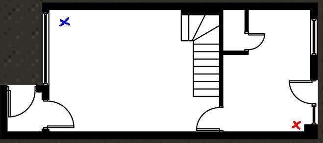
Assume the red cross is the charging station, the blue cross is the robot, no clear line of sight so rotating until it detects the glyph or QR code on the station wouldn't work. Also bear in mind there is furniture not shown on the screen grab.

GPS is a no go as it's rarely that accurate and no GPS device I own or have ever owned has worked in doors.

I2C Compass? Could that do it?

N.B. Excuse the poor screen grab of my house plan, it's all I have access to at the moment.

#9  

Doesn't Roomba use some kind of radio beacon to home in on its charger? I know it can find one in a different room, and it is not sophisticated enough that it builds a map of where it is and where it has been.

I guess a simple solution is to build your robot on a Roomba or iRobot Create and just tell it to go charge, but where is the fun in that? :)

Alan

United Kingdom
#10  

I made the assumption that the robot had ping/echo and IR sensors for object avoidance.

As far as I recall GPS is only accurate to ~10m so even if it worked indoors it wouldn't be accurate enough to send the robot home, unless I'm very much mistaken?

If it needs a lot of complicated methods such as encoders, maps etc. then the easy alternative is to place QR codes around the place so with a quick look around it will find out where it and work out where it needs to get to... or have a couple of charging stations (one for each room).

#11  

yes it uses a 360 beacon with IR omnicone receiver and IR transmitter on the charging base

OMNICONE is mostly a cone shaped mirror to refect the light or video to 360 deg IT can be used for web camera too

ROOMBA is one of my favorate platforms,one is the home base finder other is low cost,ebay mostly has them for about $50 used and just remove the vacuum parts add a 3 rd wheel and you got a great platform that can carry 35 lbs or i have upgrade its design to carry 70 lbs.

Downside is navigation cant really change it (mapping) plus not made for small robots as a platform

#12  

here is more info on the ROOMBA docking

Docking. For models with a dock, Roomba can dock itself for a recharge when it needs it. The dock projects two IR beams in a V shape. The beams are apparently coded so that Roomba can tell them from a virtual wall. When Roomba wants to dock, it will find one of these beams and follow it back to it's source by tracing the inside edge of the V. It tries to stay out of the beams so that it will follow the V gap between them. This V will lead it right back to the dock. In the case where it doesn't hit the dock at an adequate angle, it will back off, turn around and try again. Docking can be forced by manually driving Roomba back near the dock with the remote control or by pushing and holding the "clean" and "spot" buttons on Roomba together. It will then abandon it's cleaning program and search out the dock. manual docking mode is indicated by the "spot" and "clean" buttons flashing rapidly together. Docking behavior is indicated by Roomba turning and dancing in front of the dock.

The docking behavior doesn't work every time. Sometimes Roomba simply runs out of juice while is too far from the dock and Roomba stops in place. At this point, it won't do anything and it must be picked up and placed on the dock. The docking mode will work best if the dock is positioned in a location where the IR beams sweep out toward the center of a room so that Roomba will tend to run across them in its travels. The range of the beams is something less than 8 feet. The IR beams from virtual walls can interfere with those from the dock. Make sure that the virtual walls are separated from the dock by at least 8 feet AND are not pointed back at the dock.

United Kingdom
#13  

Even 1m accuracy would be pretty useless for this application though.

With the QR codes, they can be used to let the robot know where it is, not necessarily on the dock but for instance on the north wall of the kitchen, when it sees it the robot will know where it is and what direction it's facing. More for reference points than a guidance system. Not ideal but who said it was an ideal solution?

At the same time, it is presumed the robot would have the necessary object avoidance sensors as previously mentioned. With reference points that the robot can identify measuring the distance wouldn't be an issue - and distance is only useful if you accurately know how far, fast and in what direction your robot is moving.

United Kingdom
#14  

QR Codes can be picked up from quite a long distance. EZ-Script can be used to have the robot search for a QR Code, face, color etc.

The main issue is budget, not many have $4000+ to spend on having a robot self charge. I'm all about a good balance between cost and function.

#15  

NO but can easy be done with only sensors

$4000 item is for a different project nt using EZB $1100 lidar is compare to NEATO XV-11 you can get for about $110 ,already a few from this group bought one from me

Cant pick up QR codes if behind a wall or in back of the robot,my house would look very bad to have even one QR code on the wall. and mostly you need a few

QR codes not really AI navigation ,like how a person finds a way into the room

United Kingdom
#16  

I refuse to repeat myself again re: the QR Codes.

The goal is to achieve this with a budget of $0 over what is already assumed to be on a standard robot (camera & ping sensor i.e. items that come bundled in the EZ-Robot Kit). There is a way to do that using QR Codes as explained numerous times.

If that is not ideal for your situation look at the next cheapest alternative. With a combination of sensors for detecting objects, detecting direction and detecting movement along with scripts to manipulate these I'm sure it's very achievable on a limited budget.

Roomba docking seems it may be a cost effective solution but how could it be added to the EZB and other robot platforms (i.e. Wall-E or Omnibot)?

And is't the Lidar from the Neato XV-11 for object avoidance? It alone would not have the robot find home? In which case why spend a further $100 on what is already acceptable with the ping/echo sensor and/or IR sensors?

United Kingdom
#17  

My diploma in electrical engineering seems to disagree with you;) However, that aside, I was asking a question, that is indicated by the ? symbol after the sentence, not stating a fact.

I didn't say going cheap, I said small budget or a budget of nothing. There is a huge difference between cheap and cost effective. Some may have thousands of dollars to waste but if there is a cheaper alternative that's the one to promote, that's the one to shoot for, that's the one that will have more interest.

#18  

hows about a gliph...not sure how to say it, those pics with the black squares. DJ Sures says the the robots can "read" they see the gliph and it triggers scripts.

AIBO and QRIO both found the charging station and then positioned themself in the perfect spot to charge themselves, using 2 gliphs (made by sony so im assuming its the best way to find the station)

one gliph is wrapped around a small pole on the floor in the corner of a room its about a foot tall. charging base right infront of it.

seconfd gliph is on the floor right infront of the chraging station.

the first gliph (on the pole) has will run scripts that will "bring" the robot near the base and then instruct it to look down.

the second gliph will adjust the movement just right, with scripts on where to stand.

once in that position the last script the gliph triggers is to roll over the connection.

#19  

2 simple pics will trigger scripts that use the sensons and servos to get hte robot to the station....but yes 2 simple qr codes int he corner of a room. as long as the robot is constanly looking around, it will find it.

United Kingdom
#20  

I asked if compass would do it and you said it would need (and I quote) "you would need a lot more then a COMPASS..."

And again, there is a huge difference between cheap and cost effective. How many times do I need to repeat myself to you before it gets through? If ever you need to find your head I have a number for a great proctologist...

How much I'm willing to spend is a totally different issue. I'm trying to find the best way of achieving this. The best way is a balance between all factors, cost being one of the main factors to most people I have ever come across.

#21  

yep that i said ,need more then a compass,one extra fairly cheap sensor ,encoder for the motor or accelometer ,only a extra $25 more ,plus the compass to tell what heading to go I would say about $60 total cost if buy from china

IR and SONARS you all ready have,at the same time sonars and ir tells you when to stop in front of the charging base besides using them to tell the distance from each wall

With a good X AND Z map can almost use only sonars and IR'S ,and you can detect wall corners if you use the correct position and cone shape

#22  

Also what i found out since ,i have about 15 neato,s i use for selling parts and biggest item is LIDAR sensor that does a 360 deg navigation tracking

That is only use the LIDAR sensor and mapping software to find home base charger and hook up to it it has magnetic sensor to detect the home base plates

There is no transmitter or receiver on home base like the ROOMBA has can place it anywhere in the area and will return back to home base when battery is low

looks better as a platform then a roomba is ,for robots

#23  

Also RICH have you really tested the QR codes,to see if it can be pick up at over 10 feet plus distance on the wall where you have it too most rooms are 12 by 12 feet,and if in another room WILL NOT be able to see it

That a major problem of house navigation,like mine i have 3 bedrooms ,kitchen ,dining room ,plus living room and a workshop room.

robot can be in any of the rooms AND CHARGING BASE IN ANOTHER

On indoor GPS design i read while back is based on using WIFI system at the design

look it up on the internet under INDOOR GPS system

Another idea i heard some has tried is like a wall beacons on each wall with a different code for each one for home base finder AND i know few ways it can be done also

I have done lot of research on home base finder ,and different ways to try it ,more then most of us

My design uses a computer to control the charging base and sensors to guide it in (like a tractor beam) also it switches from charging to low current to keep it charged till you call for it it also uses what called ROBOCHAT to talk to the other computer (robot) ,and tells it how to find it

i cant post any info on the software because DJ said NO

United Kingdom
#24  

But that's not using the EZB or ARC software so it's of no use here. This forum is for the EZB and ARC/SDK so mapping software, robochat or whatever isn't an option.

United Kingdom
#25  

HI RichMR2

Seems to me your robot only has to do a bit of wall following to find the door at the bottom of your stairs. Dont matter which way it goes it will find the door , Then it will see the charger beacon.

Beats spending a lot of $ just to find the beacon.

Steve_c

#26  

DOOR f is very hard to go through also ,when you have about 12 inch round or square robot and still hard for a smaller one too ,i guess RICH will be using many QR codes all over his house and may be others too

#27  

yes that is what i said ,I CANT POST IT,

But ii am using the EZB to do the same thing wiith my automatic charging base and homebase finder so yes i CAN post it here

ROBOTCHAT can be 2 EZB together one on the home base and the other on a robot and using scripts it almost talks to each other

I think we all know very well RICH we cant post any software unless it uses EZB in the design,since this forum is about EZB and builder,NOW on adding the software to EZB you will need to use ARC SDK

I only posted my design that works with my software to CONVERT IT to EZB and using 2 EZB to talk to each other control the sensor for navigating to home base) i have part of it working

#28  

Automatic charging design and home base finder project ,i have working on the design for a few years

I look at and build other designs by others ,and added a few to my designs also. that why this is a major topic for me ,because i know a lot about it

Also look at wireless battery charger designs,some use SONAR to charge a battery ,and some using to coils to transfer the battery charge current to the battery by wireless one is to place a coil inside a robot and circuit to change AC inductance to DC current and another on the floor with another coil to transfer the AC inductance to the robot coil.

it does work fairly well,need to make design a little better,by making my own coils it works like a transfomer ,but without the iron core

United Kingdom
#29  

@robotmaker, it goes through the door just fine, it's never got confused there. Also re-read things, I have not said I will be using QR codes. I said that it can be done with QR codes. This discussion is about the methods available in general. If it was about my specific project then I would be posting it in that topic. As this is a community forum I try to push ideas to become more generic than specific.

#30  

do you know that for a fact ,have you built a design and had to go though a door

YES it can been done with QR codes,not the best solution,since you havent tested it first.plus has a few problems like cant see QR codes behind a wall or if the robot is facing the other direction.

BUT with sensors ,mapping and 2 EZB together letting the robot how to navigate to the room he is in is the best way.

THIS I HAVE TESTED,but not with EZB but with 2 other CPU's and software and should work the same as EZB if not may better.

So until you test the design perfect cant really say it may or maynot work

i do have a lot of projects and i am hopping to put this my home base design up soon,my main project is my johnny five project first,need to finish it before the next SHORT CIRCUIT comes out

United Kingdom
#31  

Re-read my posts, I have covered the QR codes more than once yet you fail to acknowledge the solutions to your problems

And yes, I have tested my robot going through the door. My robot will avoid all furniture in my house and roam freely around the entire ground floor of my house without a problem (other than disconnection when it get's too far in to the kitchen when running ARC on my HTPC). If I hadn't tried it I wouldn't have been able to say it's never got confused going through that door.

I have also tested the range that my robot can detect and read QR codes and explained solutions to QR codes which may be behind the robot, too far away or in another room.

#32  

please you dont need to yell,i read you posts very well Witch robot,does that you are still building one last time,also what size is your robot if its a small one then its easy.

and yes my solution does 100 % percent work ,it seems everytime i bring up a idea that i am very good at,you knock me down every time on every post

please post your design and scripts if you say it works

I cant yet .i need to finish my EZB design,but the disegn does work and tested on another microcontroller design so by porting it to EZB it will work the same . mine go though dors fine too also post a video it shouldnt be hard for you to do

IF you have a design that you said work and you SAY you are not using it,how can you say you tested it and place QR codes on the wall,QR codes does work if placing a card in front of it.may be thats you test,but you need to have a design and have QR codes on the wall with the scripts to control it ,or its not a test

very strange that the camera cant see behind the robot it only has 180 deg pan ,yet you say you can detect the QR codes and i love to see a camera see though walls to see the other QR codes,i guess you have a x-ray CAMERA i guess

United Kingdom
#33  

I do need to yell, you are overlooking a lot of what I have said multiple times, and have done it again!..

Yes my Hearoid which is still being built. Even while work in progress and far from complete it navigates doors without problems.

My design is on my showcase post. My scripts are in the scripts section and on the cloud (although made more generic so anyone can use them and not tailored to my project). Anything that is not complete or still being tested has not been posted as there is no point if there is any likelihood of it changing.

Again, you failed to re-read my posts despite telling me not to yell. The pan on the head may only have a 180 degree range but the robot can rotate on the spot infinite degrees, it can move around and search for a QR code, color, glyph, face, whatever. I'm fed up of having to explain everything many times to you.

United Kingdom
#34  

The theory behind how my robot gets through a door is simple;

2 IR sensors, one on the front left and one on the front right (these are in addition to further IR sensors and Ultra Sonic sensors that have been fitted but are not important in this maneuver)

IR sensors give a higher ADC value the closer they are to the object (if memory serves me correctly, if not then just reverse what I'm about to say).

So a script is written that checks the values. If sensor 1 is higher than sensor 2 we know that the object is to the left of the robot, if sensor 2 is higher than sensor 1 we know it's on the right. If they are equal to each other we know it's directly ahead.

When the sensors hit the specified value it controls the movement to avoid the object.

However, that said, it has always had no problems going through a door even when only using a single IR sensor mounted front and centre (which would stop the movement, rotate to the left slightly, check again, and move forwards or rotate more, counting the number of times it rotated slightly to make sure it didn't end up doing a 180 degree turn and going back where it came from.

#35  

yes that the way it works for anyone,i have about the same setup only little better

Finding the door is another problem ,but i guess you will say use a QR code on or on top of the door

I have 2 pointing forward and 2 on each side of the robot and then 2 more pointing at the corner to detect corners of the wall with very good accuracy and one in back in a sweepoing mode and each IR has SONAR with it SONARS are good at detecting some materials and same with IR one reason you need both,at the same time i have my sonars detect as small as a pencil with smaller cone same with IR too

United Kingdom
#36  

Finding the door is easy, it's usually the great big gaping hole in the wall...

#37  

yes but how with a camera not a problem using fudicals or like QR code sensors cant really do it,hard for to tell the diffence in screen door or open space ot door way or if the door it partly shut

#38  

BUT i love to see you idea how to see though walls thats biggest i see .on finding a QR code on the other side of the wall

#40  

yes i had that link BEFORE and tried his code on my basic stamp boards,it what almost my design is based off ,only i added communication to it ,and using WIFI it can be in any room

I wish i could get back on it soon,since home base charging design it what i am into then sensors almost

i test so many many designs and seen the problems it had and how i am able to make it better,AND I DID so next is to port my design over to EZB ,witch will take a little of time

DOESNT matter where the robot is the home base guides the robot to the home base for charging ,then using digital I/O i can chage the charging rate,charging current and voltage ,depending on the robot you want to charge

its universal design for any type of battery,only problem and should be hard is the charging plates i did buy a small lifting platform to raise or lower the robot or homebase to match the charging platesused,but there is other ways too.

#41  

also that parallax design is like the IROBOT ROOMBA ,i think he based it off that design

also i look at the other ling i did see before abnd i see he design is also using roomba design using beacon ,just like in the parallax link

#42  

some others may not know this but using a beacon design like the roomba or other circuits using something close to it,IT needs a clear line of sight for it to work

no tables or chairs,wall or anything that can block the IR,but i am thinking and might very easy to add is a software using IR and SONARS AND WITH A SCRIPT can make the robot go around a object in the path

ON roomba they kinda fix that problem with a omnicone that does 360 deg line of sight and they use a second beacon,,2 beaons sends out 2 signals and as the robot see one of them he turn left or right till it see's the 3 beacon and go fowardm,something like a tractor beam

United Kingdom
#43  

@robotmaker, for the last time I have not said it will see through walls. Re-read my posts, the QR Code idea was to tell the robot where it is and which direction it's facing without using any expensive GPS or compass modules. If it cannot see one it will roam until it does, thus giving it a bearing on where it is. I will not be repeating that again and until you understand that please refrain from your sarcastic comments, they help nobody.

#44  

And your sarcastic remarks too, ,please read my posts too you dont really need a compass but it does help and they are pretty cheap

AND there is a interface for the compass in EZB

ON THE GPS there is no indoor GPS yet that can be bought and GPS CANT BE USED INDOORS

my ideas might not as cheap as yours,since it cost $0 FOR your design , but it still idea i post for others who want to use it

Just like you post your idea on your idea too

i will find the post you didnt say 100 % to see though walls said it read from another room,that is why i bought up about seeing though walls

it seems on every post on any comment i make you dont like it,

on my design it may may not cost $0.00 ,but it does work better,maybe you dont think so that you

you have your point of view and i have mine and work on autocharging ock system for a very long time and a lot longer then you so i way more a expert at then you

on your design you need many QR codes for each room of the house

on my design YOU DO not need it,plus at the same time it does auto connect and auto disconnect of the charging system besides setting the outputs and current for different types of batteries

i will be posting my design very soon

United Kingdom
#45  

You just don't get it do you. It's not about finding a single solution, it's never been about finding a single solution, and I've not fixated on a single solution (in fact I've suggested more than a couple of ideas/solutions)

If you don't understand my posts (and you will know when you have to ask questions about it's content) then re-read them a few times. I make my posts as clear as possible and easy to understand yet you still get confused.

And, again, the QR code idea was not the only idea I've had on this subject so stop focusing on it, we all know it's not ideal but it's an option.

Point out the ideas in this topic that I've not liked of yours. I've flagged up that $4000 is too much for some for a guidance system, other than that justified remark what else? Don't answer that, I really don't care. Your hostility is of no help to anyone, you can't accept my constructive criticism and end up having these discussions full of me explaining everything a hundred times and you bitching about my comments... How does that help anyone?

#46  

never ever said to spend $4000 or even $1000 or even $500,to it a lot of money to pay for a navigation system ,unless you are like me,i love to testing and making very good professional robot designs

So many designs out there that others made using $1200 LIDAR and using other sensors cost a lot more.

i looking to make my designs just like thiers,i know most in this group we are in dont have the much money to spend on sensor of that high cost,but with me i like very high accuracy sensors.

big reason why i like high precision sensors is because i make very high precision testors for work.

so down to this topic ,if you have a cheap idea you like then post it,just pointing out some bad things about as there are some good things about it too,for me not going to put QR photos all over my nice walls. just like you dont want to spend money or $0 amount

my design cost a little more,but has a longer range all over the house and in any room or any part of my house

RGORDON brought up a good design he found too ,it works good ,since i tested it and ROOMBA uses a design like it,and had ideas for a few changes to make it a little better,since i know sensor s really well. and it low cost.

Only sensor i dont like that great that a lot ofrobot builders use is the KINECT its a great for NAVIGATION and so many robot schools are using it

couple of items why i dont like it and other agree ,first its a big sensor that takes up a lot of room so doesnt work well on smaller robots or look great on most of the designs here ,except roomba

second it really draw a lot of current 1.25 amps on 12 volt side and another 350 ma on 5 volt side

better and lower cost is neato xv-11 lidar about $100 and uses only 300ma

#47  

ALSO there is software for both of them too

#48  

An idea for GPS for generalized positional awareness.... All of my Android devices, becaue they use Assisted GPS (combine cell tower triangulation with GPS radio for faster fix, and fix in non-ideal conditions, like inside) work inside my house. They are not too precise inside the house, and in fact a GPS won't be precise enough outside without an expensive DGPS and long sample times, but it can at least tell which end of the house it is in, which narrows it down to just a couple possible places. There are apps that will let you share the GPS signal over Bluetooth with the computer. Combine that with a compass to know direction, and glyphs, and it can know which direction to face to find the glyph which confirms the room, and then have some way (maybe color markers) to find the door-way and start navigating to the room with the power source.

Just throwing stuff out there to see what sticks.

Alan

United Kingdom
#49  

I had thought of colour markers, or more precisely checking the wall colour so it knows which room it's in (or even what direction in some cases), which would work for my house.

#50  

Building off of Rich's idea of using QR codes, and Tech's mention of color tracking, while only using what comes in the EZ-B kit:

(I was typing this up while Rich was suggesting the wall color tracking...I like that too.)

Perhaps a script could be written to utilize both.

Color tracking would be used as a line of sight beacon. QR tracking would be used as a variable update. Ping sensor for collision avoidance.

I took the liberty of using Rich's layout as an example and added some furniture. (You have a piano, right?)
Blue X is the Robot, Red X is the dock. User-inserted image

In each room, a colored object will need to be placed in key areas. The object would have a QR code for each approach angle. I'm assuming just 3 for this example. Exact angles aren't needed as QR codes can be read successfully from some awkward angles (in my opinion and experience). The QR codes would be simple bearing indicators. In this example, I'm using compass points, but they could be anything.

A high level view of the scripting would be something like this:

  • Battery power low, activate script
  • Script would activate color tracking and rotate robot to find color
    • if no color is found, robot roams...probably in an expanding spiral...pausing every X milliseconds to perform the original rotate search again.
    • if color is found, robot color tracking forward and left/right movement is activated. (Like chasing the ball.)
  • Ping sensor is looking for a specific value to stop...assuming the ARC default value 20.
    • When sensor <= 20, then color tracking is turned off and QR tracking is enabled.
    • If no QR is discovered, then bot will adjust position and try again.
    • If QR is detected, QR updates a variable. This variable tells the robot to reposition...either back up X and/or Turn X.
  • QR variable is reset to starting value and script loops back to the first color tracking section.

Again, not an ideal set up. It might be one that someone could do with just the basic EZ-B kit, however. Also, during the color tracking movement control, I'm assuming that once the robot sees the color, it has an unimpeded path to the object.

United Kingdom
#51  

A piano in my kitchen... I never thought of putting one there :)

That's a lot like the scripting idea I had, but with more on the find the dock part (in fact, low battery script has no find the dock part currently but has low level alert to shut down lamps and space for the find the dock part).

The issue with it would be the roaming and finding it's way, obviously it would draw power so finding the dock quickly would be something of a high priority. But that said, it takes less power to pan the camera than to rotate the wheels (plus would look cool, as if he is looking around properly).

The object avoidance part after it's found the colour wouldn't be too big an issue, it knows the direction to go, if an object is avoided it diverts to go around it (i.e. turn left 30 degrees, move forward turn right 30 degrees, move forwards, etc. to go around it... a simple script using ping and/or IR sensors.

#52  

PIANO looks like its in the bathroom with a tub and sink and toliet,but i guess RICH missed that

my house it like that but no piano,but with a lot more rooms and my robot design is able to get to my home base in my workshop area very good,getting around furniture and going from one room to another,,only problem it had till i fixed it was it would run out of juice before it gets to home base

SO you need to work out first where you home base going to be,i like where it cant be seen or step on and then where the farthest point your robot will be ,and see how long it will take for you robot to reach home base before the battery dies.

And set the values in you A to D battery script

I MY house i like my walls very clean without markers of any types or it looks trashy when i have friends over for parties

IT as i idea i tried called fudicals on the wall and place them on a map using a camera my girlfriend it really look bad,i have good pictures on the wall along with wall mounted fish tanks and i try to keep it very clean for company

BUT other if they want to do then great,

i am hopping DJ makes a object recognizer add-on it may work great for navigation

but from the many systems and home base finder designs i tried,seem at least for me is using 2 EZB with WIFI one on home base and another on the robot,that way in any room its in it ,home base self giudes the perfect path for the robot to return to home base

plus it can read its battery voltage,and control the battery charger circuit and a lot more and use the camera to check if a person is in the room ,so it will stop,long list on what a second EZB can do

#53  

Josh, can you breed Babel fish? Mine keeps dying.

United Kingdom
#54  

I don't see how having a second EZB on the base would aid in the first one finding it, without the robot knowing where it is somehow the base wouldn't know, and if the robot knew then it would also know where the base is (unless the base is mobile). How would it work? What else would be needed on the second EZB?

#55  

By using its sensors on the robot and sensors on the second board and using a map it self guides like a tractor beam works,same type of idea that another person is using on using 2 basic stamps also it monitors the robot for any problems that might come up.

THE SECOND BOARD has a map and it locates where the robot is in the room , also does a lot more functions then guiding the robot,can have camera on the top of charging design to watch out for people before he enters the room and so many other stuff,like connecting and disconnecting the circuit,, and setting current for different robot designs witch i made

Sensors on the charging design it guides it in to make a good hook up to charging plates ,tell robot a right turn or left turn or come straight using 2 sensors at a angle and one sensor in the center

Sensor in the center would be the middle of the charging plates

same idea is used on 2 robots also,i think robosapien model has it built in,it knows how the robot makes a move and dances with her

another problem i have seen ,it it needs a second source to keep the board on,while charging,not a good idea to charge and run the circuit at the same time,so there is a relay on my board that disconnects main battery and uses a backup,second idea is using 2 different charging sources.one as a charger and second to power the robot

main reason to disconnect battery from the robot,all charging circuits monitors the battery if it has a load on it it wont charge it correctly ,because of the sense circuit on the charging design

United Kingdom
#56  

That's not much clearer. What sensors on the second board are needed? What is this map? Is it part of ARC? How does it know where the robot is? Can it see through walls and around corners?

Wouldn't the sensors on the robot be used by the robot's EZB and able to line up correctly without the second board?

I charge my battery while it's connected to the EZB and have experience no problems with charging. I don't doubt it charges slightly slower but it charges fine and balances fine. After all, the robot can switch to low power mode and wont be doing anything while charging so it will pretty much only be the EZB being powered and what's the current draw on that?

#57  

@ckclik (Troy) LOL

@RichMR2 can you send me an email? I would like to discuss something off the board. alan at thetechguru.net

Alan

#58  

Another thought about a second EZ-B guiding the robot back to base, it could control lighting. So, lets say, instead of colored objects that the robot is looking for, it's looking for colored lights.

The second EZ-B activates the lights when the robot runs low on power. Essentially, it would be creating active waypoints.

Hiding LEDs in a room is probably easier than having a solid object.

Which I think is similar to what Robotmaker mentioned in one or more of his suggestions, using IR Sensors...but, I'm not entirely sure. (Sorry, dude, but you speak way over my head sometimes.) :)

#59  

Hmm... Web cams, even without removing the IR filter see IR LED's as blue(ish). Embedding a little IR LED in the wall is a whole lot less noticeable than sticking a QR code on the wall.

Maybe DJ can add recognition of blink patterns to the camera control, and you can have a series of LED's that tell the robot where it is and let it just follow the lights to the charger..

Don't know that you would need a second EZ-B to drive the LED's. Probably able to do that with a simpler circuit.

Alan

#60  

great idea MCJEFF

ON circuit to drive a LED it pretty easytimer like to make it flash

I HAVE IR receiver in my wall bnut near my TV with using USB-UIRT module i can set any stations,and volume and long list of others without using a remote

And the system controls my 3 large flat screen tv in any room and any stereo,plus X10 system and lot more

one reason i am hopping DJ can do is make a script that we can add our own IR CODES.to get the code is simple just need a free software and usb-uirt and use the learn mode

on the EZB WITH NEED A SPECIAL IR receiver board i am designing and roomba output pin DO

but back to this post with a second there is a lot of add-ons to control and read

like another problem ho does your robot find a way back to home base charger when the room is dark pretty simple on home base second board it checks the light level (lux) and turn lights on as needed

and thats another ba d item about using QR codes you cant see them in the dark but like aways RICH has a answer for it

#61  

Also RICH i told you but i guess you missed in my post it mostly uses IR and 3 of them then adding sonars

second the map is from a different software

DJ has a map you can add to EZB look in the manual tells how to use it,its not great but it may work ok.

on the board i was using it has 125 digital I/O 8 analog ports and 8 IR ports plus alot more like accel and compass and servo and motors with encoders ,WORKING little at a time to PORT IT to EZB

I love the EZB more then most of the guys here,and want to use it on almost every project except ROS that uses LINUX

Second i like to build other robot designs and compare to EZB and other robot designs

FEW REASONS i do this first to learn the deign ,second to use part of the design on EZB or other designs and third to test software and compare results my first robot processor robot i made was using 6800 cpu AND ANOTHER was the SINCLAIR Z80

THATS WHY I MADE MANY home base finder designs

United Kingdom
#62  

Coloured light waypoints could be a good idea although the issue I can see with them is what happens when it's daylight and the sun is shining in to it's path? Would the robot be able to detect the waypoint?

Visually looking for the way home will always have it's issues. Natural light and lack of light are both things that need to be gotten around. If going down the visual route then more than one way would be more than likely required for 24/7 functionality.

Not quite sure how the EZB can turn on the lights if the light level is too low, sure it would work if everyone had an X10 or other home automation installed (and it's easy to do with the HTTPGet and EventGhost) but again, it's adding to the cost. $69 plus shipping plus power supply etc. for an extra board, however many hundreds of dollars to install X10 (which isn't without it's own problems)... A solution but one for those with a lot of extra cash lying around which rules out the majority.

The Roomba IR beacon idea sounds like the better option but with a great lack of usable information on how to get it set up and working with the EZB and ARC software it doesn't help much.

Another idea could be to use sound, an audible beacon. The function added recently to use stereo mics in the robot to detect direction of sound would make it pretty easy for the robot to know where the dock is but again it's not without it's problems (ambient noise, noise of the beacon)

#63  

the x10 SYSTEM RICH IS system i have already ,and it not solution for for finding home base,plus the cost is very high,sofar i had it for more then 15 years without any problem yet

and yes the EZB can turn on lights at a very low level even darkness,the senso goes well below 1 LUX witch is no light and 0 is darness,the sensor is very cheap $2.00 for LDR (light depended resistor) and a simple resistor in seies with it to ground

that what i am expert at SENSORS tested all most every sensor made and even very special sensor at work i am electroc designer,so circiuts to me are super simple any type to to turn on a light all you need is a optocoupler and traic and 2 resistors ,all parts are under $6 total optocouple is moc3011 and if using 220 volts its moc3021 (i think) i only use moc3011 for 120 volts AC

to make it dim ,need a few other parts

eventghost it a great software,but it has no sensor to tell if the light is down or window blinds are close in my house when my blinds are close and no sun ,very little light is seen now in eventghost you can set the times ,but also you need a interface X10 is one way ,HIGH COST

AND EZB fairly low cost at $70 for the great board plus $2 for sensor (photocell or LDR) and SSR relay using moc3011 and a traic

Roomba design you need a roomba platform or build the circuit ,receiver and transmitter,witch to build it is cost some money too about $60 to $80 a nd it has problems mostly it cant track right with furniture and other stuff in its way.ROOMBA kinda fix it wit 2 OMNICONES TO 360 deg pan but still buying a roomba with the homebase charger ,witch i buy alot for omnicones is near $#75 used on ebay

plus problem of putting the platform on your robot design

i guess since there is 2 names with RICH going to call the other guy RICHMR

on the sound idea kinda sound good ,but would need special filters to block noise or use sound encoders called tone detectors LM567.witch the circuit is easy and iuse that chip many times,but does take a lot of parts the make at a high cost too. out of my head i know most chip part # pretty easy ,only semi-bad at programming

United Kingdom
#64  

I never knew you were an expert at sensors, if only you had mentioned that before...

Please explain how in the blue hell you expect the EZB to turn on house lights? Short of connecting it in to the house electrics, rewiring the lighting circuits and switches to allow a permanent live at each light fitting, figuring out a way for the switches to work too, wiring it via relays back to the EZB it wouldn't work. It certainly isn't feasible to do it and would need to be carried out by registered electricians holding the correct qualifications and registered with the correct governing bodies in some countries.

For the record, although not related to this specific discussion, EventGhost can know everything there is to know about your home automation, and home automation needn't cost a lot. I wont go in to details here as this is not the correct site for that but I suggest you check out the eventghost forums if you are interested.

No need to call "the other guy" anything, but it's great that it's confused you ;)

I didn't say to use the Roomba platform I said to use the idea. The IR beacon. Since you are the "expert at sensors" perhaps you could explain clearly how it is achievable without the Roomba, so far you've pretty much just typed a bunch of jibberish that's barely understandable and goes over everyone's head (not meant in an offensive way). Explain it clearly, how it works, what goes where, how it integrates with the EZB and ARC.

#65  

there are 2 names with RICH i meant the other guy RICHMR,kinda hard to post to both people with the name RICH, when some of post are for him sometimes ,you see like you might be a new commer to this forum,first WELCOME and hope to see some of your designs RICH unless you want to be called by other name i am FRED

Now on you problem you said about lights using EZB most lights have socket that plugs in to outlet ,you put a simple homemade adapter box .like the way X10 HAS and 2 low voltage wires go to the digital port on EZB and with a simple script you turn on the led inside the optocoupler box has a male plug on one side and female on the other side.better to use metal box they are fairly cheap about $5 for a s mall box with lid,i can put up the part # and picture on how easy it is to make it so you dont need a registered electrician

just like X10 SYSTEM witch i have over 100 modules controlling everyhing in my place

yes i love eventghost it is a very good software

i know my posts are long and sometimes are to read,main reason i write it fast

on IR BEACON idea you have 3 IR transmitter (IR EMITTERS ) and setting 2 at a angle and then one in the center and using EZB witch this forum is about and not about any other processor or software like DJ said

THEN you have a receiver on the robot,should have a omnicone for 360 pan,i dont know if you know what it is,since i dont know your backgound of what you can do

Then using scripts when the robot is out of the coe area.by that i meen the 2 ir transmitter ,like if if on the left side in script to tell it to go right a little and same with the right IR transmitter until the robot is in the center then he moves forward to the charging base not good at drawing ,schematics yes on software is mostly scripts arduino and basic stamp

RICHMR is great at software so he might help with the scripts or i might ,since so far they are super easy ,while back there was a post done that some added that they are good at and what they lack in,sowe can help each other build a better robot

also i put a little more time to make it readable ,i do hate writing ,only love electronics and been working at a company for 21 years design very high in-house test equipment and testing high precision sensors ,plus i tested and bought almost every sensor made.

#66  

RICH can you tell what you are good at,would be nice and helpful to others to know what each other can do,and at the same time we can help what you lack in

Also you can call me robotmaker ,but FRED is better to have a good friendly forum that each person has a good talent,it great to be called by the his name but it is hard sometimes

i did look over my last post where you said it was un-readable and only saw a few words missed spelled from righting it fast

i did seperate the sentences so easy to read,so if you can point out whats are to read i can fix it,kinda hard to right about a circuit with out a drawing (sorry just not good at it and mostly dont like art too)

But schematics are super easy for me ,but takes time,also i have a very good electronic photographic memory,,i wold make a good spy recruit because i can look at a schematic and latter remake the circuit on paper or in a schematic program and chips are the same for me too

#67  

What about using a laser pointer like this....

User-inserted image

User-inserted image

User-inserted image

User-inserted image

Summary of previously discussed issues that must be solved:

  • Robot needs to recognize when it is time to head to the charger.
  • Robot should turn off all non-essential items to conserve power if possible.
  • Robot needs to know what room it is in.
  • Robot must know how to navigate back to the room where its charger is located.
  • Robot needs to recognize when its batteries are fully charged and must execute a maneuver that will
    back it away clear of the base station.
  • Detection of an object blocking the robots path to the base station will override the hunger function.
    The robot must deal with (go around) the obstacle and then resume searching for the base station.
  • Battery charger contacts must not be "live" until the robot docks with the charger due to safety concerns. Several methods would work for this.

New issues involving using a laser that would need to be solved:

  • The sensor head assembly on the robot and the laser pointer at the charger must be exactly the same height from the floor. Not hard to accomplish.
  • When in hunger mode the robot should send out a signal that activates the laser pointer so it is not on all the time. May be able to use a key fob like the ones used with car door locks. I know several sites that sell them.
  • Must find the appropriate type of sensor to use. Are there any that are made to detect lasers? Does there have to be anything special about it?
  • How many sensors are needed on the sensor head assembly?
  • Robot should be able to make minor course adjustments to keep the beam focused on the middle front sensor.
  • If contact with the beam is lost, the robot should go back into hunger search mode.

PROS

  • Not affected by room lighting conditions.
  • More directional than IR source, sound source, or L.E.D. source.
  • Good range.
  • The way it senses the beam causes the robot to be directly lined up with the charger.

CONS

  • Laser may not be good for some because of pets or children.

    Please let me know your opinions and ideas on using this method. Thank you.

United Kingdom
#68  

@Robotmaker, as fun as it is to see you get confused and as much as I'd love to see how long it takes before you realise but, I am not new here. A simple username change in the settings was made to drop the MR2 part of my username. I'll pick apart your posts when I can be bothered.

United Kingdom
#69  

"Now on you problem you said about lights using EZB most lights have socket that plugs in to outlet ,you put a simple homemade adapter box .like the way X10 HAS and 2 low voltage wires go to the digital port on EZB and with a simple script you turn on the led inside the optocoupler box has a male plug on one side and female on the other side.better to use metal box they are fairly cheap about $5 for a s mall box with lid,i can put up the part # and picture on how easy it is to make it so you dont need a registered electrician"

Most lights are wired in directly and ceiling mounted or wall mounted. The light can be wired one of two ways, either with a switched live, neutral and earth or with a permanent live, switched live, neutral and earth. Method 1 would be impossible to control via the EZB until the wall switch is in the on position as the live at the light wouldn't be energised with the switch off. User-inserted image

Method 2 may be possible as there are both switched live and permanent live at the light. But, to tap into any electrical circuit and make the modifications required, at least in the UK but advised worldwide, it should be carried out by a registered electrician and depending on location may require Part P notification (UK, this may vary in other countries). User-inserted image

To have an EZB control these lights it would mean that changes to the house wiring would need to be made no matter how you look at it, or installing modules that can be remotely controlled and a way to control them from the EZB or PC.

It sounds like you are describing smaller table lamps or desk lamps which plug in to electrical outlets which generally are not found in all rooms, tend to only provide ambient lighting and are not what you implied previously. Either way, these would need extra wires run to the lights from the EZB, you may not want QR codes stuck all over your walls but I'm sure as hell going to bet people don't want extra cables run around their house, running across floors, clipped surface to walls etc.

Also, a second EZB could require a second PC, so even more cost added to it.

That doesn't sound like a very cost effective or feasible plan to me...

United Kingdom
#70  

@rgordon, I have a script in the cloud and scripts forum that monitors the battery voltage and acts on a pre-set low voltage alert. This will work for switching to low power mode and hunger mode.

Similarly, a similar script could be used to detect a fully charged battery

#71  

in usa its very easy,i been to london and UK may times ,but i never seen wow a house is wired BUT IN USA at least in my house i have mostly table lamps. with a few ceiling lamps

At the same time since we make electrical testers for electricians and i do my own out replacing or fans or anything else that goes bad,thats why be have a homedepot in isa that sell the stuff for home repairs and books on homeowners to do repairs like that we out having registered electrician

ONLY thing we can touch is the main wiring comming in to the main box

SO its pretty easy and low cost,i dont now about in UK ,plus you dont need much equipment and not dangerous if you shut off the breaker first

On the laser idea RGORDON has its not a great idea ,one is the laser unless you use a low class laser can hurt a persons eye ,unless it low to the ground ,very high cost,mostly the receiver end but it does work well in low or no lights

Good to see others have ideas on ways for this to work i can put what i know ,since ihave made and tested almost every type of design its good and bad about them.

AND you dont need a second computer it has bluetooth or can use WIFI and EZB can have 5 hook up to the same computer at the same time

you dont have to have wires all over the place also ,it more like making a X10 BOX my friends will say my house will look very bad with QR codes posted all over my painted wall,plus what about the lighting you cant see QR in the dark

And how do you control the lighting also,only 2 ways one is make you own X10 system or buy X10 system

#72  

Second item i didnt add you do not need to wire every light in you house,only a table lamp is need most room i know in a house has atleast one or 2 table lamps ,and you only need it where the homebase charger is too,might can even add a dc light might work too.

IN my house i have every outlet ,every light,pool,spa and A/C and heater design (made by me) and alarm and outdoor lighting controlled by X10 and a powerfull antenna made for X10 ,so i dont need to make a box yet.

But others it would cost too much,but i do no another on this forum who has a X1O system and may be more.

And at the same time if i want to use a computer for a second EZB istead of one computer controlling all my EZB ,i have whats called a network house,every room has at least one computer,including my favorate area the kitchen where i need it the most.

But still DJ made it so EZB you can hook 5 to one computer and control more then 5 too i tried it and it works well ,since i have a lot of cages and fish tanks in different area's and making them controlled by EZB there is another guy my buddy JOSH started the idea.

So you dont need a second computer

United Kingdom
#73  

If it's an issue of maintenance it can be carried out by anyone (which is why you can buy the parts) but what you have suggested is a lot more than an issue of maintenance, it's a partial/full rewire of the lighting circuits!

Wireless connections from the EZB to the lights? How? Short of using RF or X10 methods and additional PC software, hardware and adding in modules it would need wires from the EZB to the lights, outlets etc.

It is not financially feasible nor is it simple. The ideal solution would be available to everyone regardless of country, money, knowledge and ability.

There are more than 2 ways to control the lighting. I don't own any X10 stuff but can control my lights anywhere in the world, or from any sensor "witch i is am excert in", or timed or well, anything. But that's a totally separate discussion and non-ezb related, you know where to look for the info on it, I have told you before.

#74  

you can control any lights from any where in the world,but you still need to first buy it ,higher cost then about $10 for the box idea i have,you need a controller more then $60 for EZB you still need to wire it in.

only other idea is easy stay up at night or leave you lights on all the time,main problem with homebase finding or navigation using a camera is lighting.

Using EZB board does a lot more then turn on the lights it monitors the robots and controls and guides him,second it controls the charging design (my favorate part) and add other controls or monitor sensors as needed,plus another project to use the EZB

And on wiring its pretty easy not fully wiring it like you said its only 3 wires is really needed power (hot) neutral and return ,most ceiling light you but or already installed most have 2 black wires, and pretty easy emove the wire nuts and add the box in between it with 2 extra wire nuts.

I can make a schematic ,but its pretty simple and not needed and i said there is a very easy way just use a lamp

IF you know a cheaper way then about $70 total for the project $10 plus $69 for EZB I love to see it

There is no software in the world that can turn your lights on without a interface witch meens very high cost

#75  

@robotmaker Yes I would keep it as low as feasible. Laser pointers are cheap. Don't know anything about what type of sensor I would need or how many would be needed on the head assembly. Could you use a photo transistor or photo-cell? Never tried using them with a laser. If so these are very cheap. I'm still searching. I believe the laser idea is worth a try because it is such a focused beam to follow. Who knows this could also prove to be its downfall I guess with having to track such a tight beam. I will keep you posted on any test results.

@Rich What I definitely will need is some coaching on coming up with certain scripts to control robot movement to track the beam and stay on course. Would you (or anyone else) be willing to answer a few questions now and then or help me brainstorm ideas on this endeavor?

I guess the most important thing to solve first though is getting the robot to know how to get back to the room where the charger is located. Without that resolved the rest would be a moot point.

BTW please feel free to call me by my first name.... Rex.

Cheers

#76  

REX Laser light is not the problem ,its the receiver part added to it makes it high cost,it also needs a good optics,and filtering design,photodiode is needed to match the wavelength of the laser,plus a special amp design and more

Also on using a laser circuit you should have 3 of them or 3 receivers to work like a tractor beam idea to steer the robot it or scanning design but that takes alot

I have a laser optical bench at my place and witch i tests lasers and circuits ,i have a few red and green laser modules ,some very tight beem some put out a laser line and making a good receiver circuit not easy.

I guess i can get my data and post a schematic on it,BUT it does need a lot of parts

IR roomba idea is a lot more easy to build and no optics is really needed,should have a omnicone,but can take apart a cheap roomba charger home base unit apart for it $8 on ebay or less and you have a IR photodiode that matches IR wavelength

and use FRED is cool,good to have a first name in this forum

I WAS wrong about the price on about $70 for laser receiver its $70 per each laser RECEIVER ,so about $210 ,big cost is photodiode made for wavelength of laser $15 and another $20 for optics to pass only that wavelength and not lights or IR plus to focus the light on to the diode

#77  

REX on this you said

Not affected by room lighting conditions.

  • More directional than IR source, sound source, or L.E.D. source.
  • Good range.
  • The way it senses the beam causes the robot to be directly lined up with the charger.

first one is good no lighing is needed

Second about the IR not more directional is not really true ,if you use 3 IR'S and omninicone you get 360 deg

THIRD about lining up the robot to the robot ,both can easy do it

CONS Your right at that on cost is very high,when i made mine it was near $70 and i had some parts

Also you want your contacts and laser very close to the floor as you can,like on roomba base

scripts to line up the robot with IR or LASER is the same,center light he goes forward if hits a right beam he turns left to center beam and same with left beam

BUT main problem with both is that they need a light of sight,meens no furniture in its way one reason a good map design , and hope you dont move or change anything in your house

now there is other idea ,use the ceiling it never changes ,and they design systems for it,but if using fans is a problem

These are things i found out testing almost every design ,

#78  

Since i love using lasers alot and have many neato xv11 lidar for navigation

there is a way to lower the cost on the laser IDEA ,scanning the laser ,still need $70 circuit but with a pan servo circuit

The laser with start panning until it hits the receiver then robot moves forward and scans again and depending if he needs to turn left or right to follow the beam

It will need a lot of scripting ,but it does look better

And 2 ways to do it ,scan the laser or scan the photodiode ,both will take another servo's plus pan brackets ,but at least it may cost you about $100 total ,lasers on ebay are about $5 to 7 $ for a spot laser module and you would get a red one not green,green is for special designs

United Kingdom
#80  

@Rex feel free to ask any questions, that's what the community is all about.

The laser idea could be kinda cool, and if tied in with a second EZB it needn't be on all the time, but that is an option available to those who can spare the extra $100+ a second EZB (plus things to make it work) would add.

#81  

YES i think so too,one reason i am looking at getting the circuit together and soon make a schematic and parts needed ,and may be the scripts ,i would take about $170 total including a second board

Other idea too ,i dont know if it would work and sold wwell over 20 of them at about $110 each is a laser with optics and receiver and microsoft with software called LIDAR for navigation,thats uses on neato XV-11 vacuum cleaner to to find home base a connect to it, few guy here got one from me

DOES need some coding,but API CODES are made and works very well with LINUX ROS witch has the drivers for it

so no circuit needs to be made,an email for more info on it jamericanfreddy@yahoo.com i have 10 left till i buy more from neato company and they sell fast oin ebay,just this week a lady in france bought one to place on her quadcopter ,very cool idea

#82  

Jumping back to the idea of providing navigation illumination from a second EZ-B (not that I think this is the best idea, just examining the options). Your robot does not need enough light as a person, just enough for the camera to see. EZ-B can easily turn LED's on and off, and you can get some very bright ones, and they are very low voltage, so perfectly safe. So similar to my idea of providing IR LED's with different blink patterns in each room (still need pattern recognition added to ARC or someone - maybe me one day, but not soon - needs to do it with the SDK), you could also discreetly locate bright white LED's for illumination.

Personally, I am going to have an IR camera on my BOT with the IR illuminators on the bot, so no need for room lights, but I think this simplifies the solution considerably from trying to interface your bot to your home lighting. That being said, there are tons of home automation solutions that could have the computer that drives the bot also control house lighting and other things too, but I think we are looking for cheap, easy, and reliable and most home automation only meet two of those three criteria at any time.

Alan

United Kingdom
#83  

I completely agree Alan. I have no reason for using an IR camera as I can have my bot turn my lights on and off as needed but my situation is not the norm and I cannot base a solution on things I already have in place... so the IR camera is a great idea and solves a lot of the issues.

Even the camera which comes in the EZ Robot kit doesn't need much light, I have a very dimly lit house, it struggles with face recognition (phantom faces) but glyph and qr codes it picks up fine in low light.

If using a second EZB the option of a camera on the dock with custom object recognition using harr isn't out of the question. it would be a lot of work, it would be a bit extra cost but it would be very reliable... Robot gets in to line of camera on dock, dock recognises it as the robot, dock controls the robot and guides it in.

#84  

Going back to @rgordon's excellent summary of the issues and possible solutions, #1 was detecting the need to charge. What are people doing for that? I am sure it would involve one of the analog ports of the EZ-B, but what are you using to convert raw voltage into a low voltage signal EZ-B can read? How are you calibrating to your batteries? How are you sure what is low enough to still navigate home without dying on the way? Etc....

Alan

#85  

YES THAT i being try to say to use a econd EZB so much you cann add sensors or relays or lights and have to cotrol your robot,if if you have progamable charging design even better

I made one and had 2 boards made for it and soon hopping to make many more boards to sell DESIGN is set up to charge almost any battery made and have adjustable voltage,current and c rate plus when done goes to trickle charge

United Kingdom
#86  

Alan, check the cloud, I uploaded a simple battery monitor script a few weeks ago which uses the ADC port(s) to monitor the battery voltage.

In fact, let's put the code here as it will be usefull;


# Read voltage level of battery and report to software.
# Set variables
# Change $vmin to low level alert value
# Change $vmax to battery full charge
# Change $multiplyer if using voltage divider
# Factor is 5/255 for adc value conversion to volts
$vmin = 3.6
$vmax = 4.5
$multiplier = 2
$factor = 0.019607843

:ReadCells
# Get ADC values
$vc1 = GetADC(ADC0)
$vc2 = GetADC(ADC1)

# Convert values to voltage
$cell1 = $vc1 * $factor
$cell2 = $vc2 * $factor * $multiplier
$cell2 = $cell2 - $cell1
$batteryv = $cell1 + $cell2

# Log it
#FileWriteLine(&quot;C:\chargelog.txt&quot;,&quot;$date $cell1 $cell2 $batteryv&quot;)

# Check for errors on connections
Print(&quot;C1 Round($cell1,2)V&quot;)
Print(&quot;C2 Round($cell2,2)V&quot;)
Print(&quot;Ct Round($batteryv,2)V&quot;)
IF ($cell1 &lt;=$vmin or $cell2 &lt;=$vmin)
  Tweet(&quot;Melvin needs charging!&quot;)
ENDIF 
  # Wait 10 seconds
Sleep(200)
# Go back to the start
Goto(ReadCells)

I have adjusted it a little in my project which aren't shown in the above but the above will give an indication of how to monitor it. It is based on a 2s LiPo battery so needs to calculate cell 2 (cell 1 is easy as it is directly measured, cell 2 is measured by measuring the total and subtracting cell 1).

Also, $vc2 is generally above 5v so has to go through a simple voltage divider to halve the voltage recorded, the script then multiplies it by 2 before using it as a value.

The $factor is 5/255 as the ADC ports measure up to 5v and report a value of up to 255 so it needs converting back to volts.

I made a few adjustments to the above after copy & pasting as it looks like I had messed with it for checking the charging circuits but it should be clear and work for monitoring. I'll revisit the script later when I get home but off out now so in a bit of a rush.

#87  

Thanks Rich. My bot will have a 24v 17Amp Gel Cell to drive the wheelchair motors as well as some buck step down regulators to drop to 19 volts for the Netbook and 6 or 7 for the EZ-B. I am sure I can't connect that directly to the EZ-B ADC port or it will get toasted. The regulators I bought provide constant voltage until the input is within 2 volts of the output, so I can't measure from them. I think what I would need is to put resistors between the battery and the ADC so I am measuring relative voltage, not actual voltage, but it has been 30 years since I did any electronics, so I am a bit rusty on the specifics.

I am sure others have discussed this here, so I will do some searching after work and post links or conclusions to anything I find.

Alan

#88  

CAMERA works kina well with IR do need s9ome changes done to make it work,i know i tried a webcam to pick up a IR source and it didnt pick it up well ,very blurry and a big filled screen on the camera

thinking the same with a bluetooth camera too,and webcamera are much better ,only USB so both have good points and bad points

#89  

thats what i have on one of my designs ALAN one reason i designed my battery charger to handle up too about 100 amp battery at 24 volts ,or 12 or 6 or any voltage of a battery

so a battery like yours would need about 5 amp charging rate at 3.4 hours and thats mostly a fast charging rate,idea rate would be 2.5 amps at 6.8 hours,but mostly depends on what the charging rate that the company says to charge it at

#90  

TO measure voltage on a bettery is not really the best way to go,but it can work ,but checking each cell voltage

what most company who designs battery chargers ,they use a simple current monitor ,using a low ohm resistor or a hall effect design with analog output

thats what we use at work since all our test equiment mostly use batteries one of the big test equipment company we bought is AMPROBE ,factory not in new york any more,looking at next to buy FLUKE

But i think FLUKE wont sell yet

United Kingdom
#91  

Alan, ill post the voltage divider schematic later too, its simple enough and measuring voltage on adc has been 100% accurate for me so far.

#92  

Robotmaker and Rich, thanks both. I'll research Hall Effect (I have seen it mentioned here before) although for this purpose I too think voltage measurement will be sufficient. Just want to get home while there is enough juice to run the motors. Everything else is lower voltage so should keep running long after the motors can't go.

For the charger, I am set already. I have an electric wheelchair charger designed for this specific battery.

Alan

#93  

I like wheelchair motors great for large robots that weigh about 200 lbs or more mine about 150 lbs may more once i get my arms done,i have my macnine done with every machine needed ,lathe and a mill are the best for it ,next is to buy a very good 3d printer .i saw a nice one for $4800,so for me its easy for me to buy it,just need to do more reseach on it and make room for it might add another room on to my hose i need it

ALAN you adding arms to it, also on chargers i hate buying them,mostly made for the battery it made for .or not higher in current or voltage,witch meens every robot a person makes you need to buy a charger for it

Now on LI-POLY battery,i may or may not buy it,it does take CC and CV to charge a battery and the circuit not hard,plus you need a cell switching board,depending on the cell count

#94  

ALAN you making a wheelchair setup ,when you said about getting home without the batteries doing out,if yes that very cool i seen a few and one is controlled by EEG headset ,witch i bought 2 types to use on EZB its done with using arduino,so should be easy to port to EZB it uses you mind to move and control the robot

United Kingdom
#95  

A basic voltage divider, set up for 1/4 of the battery voltage to ADC0 User-inserted image

If you only need half then replace R1 for a 10k resistor, if you need 1/8th then replace R1 for 70k... basically, equal resistance either side of the signal wire will halve the voltage, increasing one over the other will vary the ratio. For less voltage to ADC increase R1, for more increase R2. I don't run mine with R3 connected as I didn't have enough resistors but it's apparently advisable to add in a 10K as R3.

Then you can monitor the voltage on the ADC port by running the GetADC(ADC0) command in EZ-Script.

My actual script I use to monitor my current projects 7.2v 2S LiPo is;


# Read voltage level of battery and report to software.
# Set variables
# Change $vmin to low level alert value
# Change $vmax to battery full charge
# Change $multiplyer if using voltage divider
# Factor is 5/255 for adc value conversion to volts
$vmin = 3.6
$vmax = 4.5
$multiplier = 2
$factor = 0.019607843

:ReadCells
# Get ADC values
$vc1 = GetADC(ADC0)
$vc2 = GetADC(ADC1)

# Convert values to voltage
$cell1 = $vc1 * $factor
$cell2 = $vc2 * $factor * $multiplier
$cell2 = $cell2 - $cell1
$batteryv = $cell1 + $cell2

# Check for errors on connections
IF ($cell1 &gt; $vmax or $cell2 &gt; $vmax)
  Print(&quot;Battery Connection Error&quot;)
  
  # Check for errors on cells
ELSEIF ($cell1 &lt;= 0 or $cell2 &lt;= 0)
  Print (&quot;Battery Error&quot;)
  
  # Check if below recommended levels
  # Cell 1
ELSEIF ($cell1 &lt; $vmin)
  # Do sometihing if voltage low
  Print(&quot;Cell 1 Low&quot;)
  
  # Cell 2
ELSEIF ($cell2 &lt; $vmin)
  # Do sometihing if voltage low
  Print(&quot;Cell 2 Low&quot;)
ELSE 
  # Wait 5 seconds
  Print(&quot;C1 Round($cell1,2)V&quot;)
  Print(&quot;C2 Round($cell2,2)V&quot;)
  Print(&quot;To Round($batteryv,2)V&quot;)
  Sleep(5000)
  # Go back to the start
  Goto(ReadCells)
ENDIF 
  # Go back to the start
Goto(ReadCells)

If there is an error connecting to the battery it will report it, this is determined by an ADC value of over the maximum voltage of the battery, as my batteries cannot get above 4.2v when fully charged I've added a slight tolerance and set the $vmax to 4.5v. With the battery monitor cables disconnected the ADC value returned is 255 so will report a 5v level and output the error message or run the error command.

Again, if the ADC is low, as in 0v, it will report a battery error and, if required, run another script or other functions if needed.

Then the monitoring script checks the current voltage against the preset minimum voltage. Once the minimum voltage is met it reports it as low and can run another script or other functions if needed.

While the voltage is OK the script just loops around reporting the voltages for information.

I did plan to include an LCD screen but the one I got was I2C and no datasheet so couldn't get it to work correctly, but that could be added in easily. As could additional cells/batteries, less cells/batteries, setting it to illuminate an LED for low power, shutting down for power saving or most importantly, running the find home script to get to the dock to charge.

I'm still developing the script but as it stands it works so feel free to use it, modify it, have fun with it. Hopefully the comments and the above descriptions will aid in adjusting for your specific requirements.

P.S. I believe all of the ;) in the code are just closed brackets )

#96  

Rich, thanks very much for the data. That looks like it should be easy to implement and meet the needs.

Robotmaker, I am using wheelchair motors for the weight carrying, and in some cases for the speed. The bot will actually be sort of dog shaped (think k9 from Dr who, but with steampunk decoration when it is done), but will also have fold down foot stands (like motorcycle passenger foot pegs) and an attachable handle with a joystick so I can ride it standing up, sort of seqway like.

I want it to be under 50 pounds so I can take it on Amtrak as luggage, but I think it will wind up 60-70, but since I am an employee, I can probably get away with telling them it is for personal conveyance and exceed the weight limit. I am 225 lbs (although trying to get down to 200) so I need the power of the wheelchair motors to get me around, but they themselves, and the battery are almost 50 pounds before I add the robot body and other parts. Motors are rated for 300 lbs, so should be OK carrying me.

Most of the time though, it will be autonomous and one of its jobs is guard dog, which is why I want the speed ability of the high power motors. I want it to be able to go fast enough to scare the cr-p out of any intruder in my home.

Alan

#97  

Thats a cool idea ALAN

RICH on you divider circuit looks ok.,i would add protection,put that me i look at very high precision ,mostly i use to it and safety I use alot of it at work in inhose tester i design and make and calibrate with even much higher precision equipment ,last peice i finish last week was very hard 4000 amp tester for clamp-on meters for FPL

United Kingdom
#98  

My divider circuit doesn't just look ok it is ok, it's been installed and working without a single glitch for the past 6 weeks or more, without R3, accurate enough for it's purpose.

#99  

Others dont also look at the time the battery is is going dead and depending where you have you need juice to get it back to the charger.

SO you need to add that to you low battery voltage,best way is move your robot to far away point in your house and check to see how much current is used ,kinda hard with a voltage monitor design

Only other way is to wait until is dies and re-adjust the divider again and may again You dont want to charge a half dead battery on gel cells ,main reason is called memory effect ,on LI-POLY it doesnt have that problem

United Kingdom
#100  

If only the script had a variable like $vmin for adjusting the low voltage alert level... whoa, it does... But we should really have said about figuring out how much power may be needed to get to the dock... holy cow Batman, would you look at that, it's already been said...

Is my sarcasm too much? :D

#101  

RICH yes its a very common circuit its used in almost every type of voltage design and have made voltage divider latters using 9 to 10 resistors in series with tap off points

,i guess you read me wrong on what i said about it when i said it look ok,it meens ok, just i work for company that looks for better more safer design ,6 weeks is a short time for precision test equipment where we look at many years or more

and accuracy is not needed for robots ,mostly just a toy

United Kingdom
#102  

Why overcomplicate things when they don't need to be overcomplicated?

I'm guessing that if I said I went on holiday to tenerife you would have been to elevenerife...

Expand on this protection, these improvements, be clear, part numbers, values, where in the circuit it should go and why it's needed. It's all very well saying "you should have protection" but how does that help anyone? What protection, put a seatbelt around it?

I apologise to everyone for my sarcasm tonight. It's now either laugh or cry I think...

#103  

About protection for it if a resistor goes bad,(very unlikely) or cold solder point over time (very likely ) seen many of customer returns wth this A TO D will be fried full 12 volts from R3 and R1 and i am talking about R2 going open may be not your but still more time is needed ,but other maybe this post is for everyone

#104  

i never ever use sacasm or ever get mad,but that me

But back to the fix its easy a zener diode so voltage never goes higher at the A-D THEN 5.2 volts it a very common resistor ,only about $.20 so doesnt cost much and at A-D at ad to ground or at R2 TO GROUND

price is lower $.15 each for 5.1 volt zener at 400ma can even go lower its not used as a regulator anode is always gnd and cathode is is always postitive on zener its black line on top 5.1 volt 400 mw zener

If too hard i can easy make it,so much work ,plus on forum to help others, sometimes have problem with what i write ,because of caps or spelling or peroids and others looking me to fix it

United Kingdom
#105  

Size, type, part number, link? Where in the circuit?

Please feel free to adjust my schematic. If you want the SCH file I'll share it so you can update it, or just save the image and adjust it in photoshop, paint, whatever and re-upload.

#106  

ok did say where to put it accross R3 but i guess you need a schematic to be more clear for you

and THANKS for letting me update you photo ,i dont update anyones photos unless they say ok

can you give sch in zip file and post it i dont use paint or like it,but i do have many schematic drawing programs

United Kingdom
#107  

voltagedivider.zip

Unfortunately a lot of what you write is unclear. Also please give more information on the zener diode, there are 99 to choose from where I buy my components...

#108  

i see only a few at digikey with that value of 5,2 volts at 400 ma

can you send me the link i love to see 99 of 5.2 volt zeners at 400 ma

divider.zip

thanks for the zip ,i didnt need it i made my own i made it small size when i converted it to GIF file i did it fast

United Kingdom
#109  

That's the first time you mentioned any values for it, unless it was hidden amongst jibberish.

can't open the zip on my phone, can't you add a jpg image in to the post to make it easier all round?

#110  

Also what program did you use to make ,i use mostly expresssch,only because i send my boards to company to have them made.

I try to take my time to write more clear for you.

like i said i write very fast and really dont have the time to adjust my writing,also i dont like to write

#111  

Also 9 years ago i had photoshop CS5,but i gave it to somebody since i dont use it any more ,i really

Love the program alot,and my pro cameras i had,but i did buy another pro camera for my mountain climbing i do alot,other hobbies i have my camera for is scuba and skydiving ,now thats lot of fun

May like skydiving more then robots

#112  

Is this you call jibberish

And it had a link to part ,check page 12 #8

price is lower $.15 each for 5.1 volt zener at 400ma can even go lower its not used as a regulator 5.1 volt 400ma zener diode anode is always gnd and cathode is is always postitive on zener its black line

#113  

Thanks Rich for providing the code and circuit example. I will try that out as soon as I can. That's the way to conquer a problem. One step at a time. Then move on and solve the next one.

Alan - I like your idea of providing IR LED's with different blink patterns in each room. If EZ-B could recognize blink patterns, it could provide lots of different info to the robot. Maybe it could recognize an LED pattern that resembles an arrow showing the robot which direction to travel.

What about an IR LED mounted on each side of doorways. When you or a script commands the robot to go to another room, somehow the boxes come on in sequence luring the robot from one room to the other? Kinda like "way points". How would you get the right box to come on in sequence? Wireless RS-232 serial?

Thanks to all who are participating in this discussion. It has been most interesting. The more minds on this problem the faster it will be resolved. :)

Rex

#114  

THAT would be hard to add REX ,first a circuit ,not hard ,but power is the problem and setting the height

REX this thread of your is my favorate,because i very heavy into home base finding and docking best reason i tested so many many designs about 20 and now i a see a 2 more to try and compare with my other designs.

Way i look it ,is try it and doesnt work try another design,some posted designs i made and i tried them they work ,just not that great and had problems,noise,or objects in the path,lighting and lot more

BUT biggest problem i seen is going from one room in the house to another room that has the home base at.

SO hope it works for you REX

FRED

United Kingdom
#115  

The zener diode goes across R3? But your schematic shows it going across R2 to ground. Can you clarify which is correct? Also confirm which way around the diode connects as it looks like it's on backwards, but that may be how it needs to be.

Added in Diode & a few notes on my schematic; User-inserted image

Part list R1 - MCF 0.5W 10K/MCF 0.5W 20K/MCF 0.5W 30K resistor rated at 10k 20k or 30k ohm 0.5w carbon film (as required, see schematic for info) R2 - MCF 0.5W 10K resistor rated at 10k ohm 0.5w carbon film R3 - MCF 0.5W 10K resistor rated at 10k ohm 0.5w carbon film (optional) D1 - BZX79-C5V1 Zener Diode rated at 5.1v 500w 5mA

I'm sure you can pick from a range of resistor types provided the value is correct and rated at a minimum of 250mW.

All components can be fitted inline or you can make a small board easily. Mine are soldered inline and heat shrinked.

United Kingdom
#116  

I have a little time on my hands now so going to redo the script for just a single battery.


# EZ-Script
# Battery Level Monitor
# Version: 1.0
# Author: Rich
# Script date: 2013-02-15
# 
# Details
# =====
#  EZ-Script to monitor the voltage of a battery via the ADC port of the EZB,
# report the voltage as a variable within ARC and act upon low voltage
# for instance triggering the scripts for self docking and self charging.
#
# Notes
# =====
# Read voltage level of battery and report to software.
# Assumes only one battery requires monitoring.
# Assumes script for low power event is named &quot;batterylow&quot; and stored in the Script Manager
# Maximum voltage ADC ports can accept is +5v. If battery voltage is higher a voltage divider
# will be required - Schematic available at:-
# https://synthiam.com/Community/Questions/2834&amp;page=13
# 
# Set variables
# ==========
# Change $vmin to low level alert value (remember to allow power to get to dock)
# Change $vmax to battery full charge (max 5 times multiplier)
# Change $multiplyer if using voltage divider
# Factor is 5/255 for adc value conversion to volts
# Change $battery to the correct ADC ports.

$vmin = 3.6
$vmax = 4.5
$multiplier = 1
$factor = 0.019607843
$battery = ADC0

# ---------------------------------------------------------------------
# -- Do not alter below this line unless you know what you are doing --
# ---------------------------------------------------------------------
# 01010010 01101001 01100011 01101000 

:ReadCells
# Get ADC values
$vc1 = GetADC($battery)

# Convert values to voltage
$cell1 = $vc1 * $factor * $multiplier

# Check for errors on connections
IF ($cell1 &gt; $vmax)
  Print(&quot;Battery Connection Error&quot;)
  
  # Check for errors on cells
ELSEIF ($cell1 &lt;= 0)
  Print (&quot;Battery Error&quot;)
  
  # Check if below recommended levels
ELSEIF ($cell1 &lt; $vmin)
  # Do sometihing if voltage low
  Print(&quot;Battery Low&quot;)
  ControlCommand(&quot;Script Manager&quot;,ScriptStart,&quot;batterylow&quot;)

  # Just output the result and loop to begining
ELSE 
  Print(&quot;Round($cell1,2)V&quot;)
  # Wait 5 seconds
  Sleep(5000)
  # Go back to the start
  Goto(ReadCells)
ENDIF 
# Go back to the start
Goto(ReadCells)

#117  

sorry i meant R2 ,and R3 is needed DIODE is only to protect the AD so it nevers see's above 5.1 volts

I wish i didnt get rid of photoshop,to convert files,a few times i wanted to post a jpeg and only have in GIF or bmp

BUT i just easy buy another program,smaller one once i get i will post my circuit back

R3 is good for noise and limits the current going in to AD, most data sheets on microcontroller to add it

And only needed on A-D inputs,some tell you to add a cap in parallel ,i dont think its needed

Good to see at least you know scripts,so far it seems easy for me but some it may not,

United Kingdom
#118  

So is the schematic now correct, with protection and the correct diode, around the right way, in the right place?

Edit: Looks like my schematic is right looking at other sources and should protect against over voltage, I'm happy with it anyway although personally I wont be adding in D1 or R3 to my current project as it's all inline and if it aint broke don't fix it.

#119  

@Robotmaker

(slightly off topic post)

you said "I wish i didnt get rid of photoshop,to convert files,a few times i wanted to post a jpeg and only have in GIF or bmp"

I know you said you don't like Microsoft Paint (and I agree, I don't use it for anything but the simplest editing), but you can use it to convert GIF or BMP to JPEG.

Also, there is a really excellent free and open source program "The Gimp" http://www.gimp.org/ that is almost as powerful as Photoshop.

Alan

#120  

THANKS i forgot about paint ,about it converting files

RICH thats not a good idea,says if its not broken dont fix it

BEST is better to be safe then sorry latter on, $.15 ITEM and may be 5 min to put is in saves about $70 LATTER ON on a new EZB replacement,but may get lucky and still wont get bad for a few years ,nobody nows what will happen ,even you

thinking $.15 is too much money or the time to add it for you

United Kingdom
#121  

I know the EZB can take 8.4v on the ADC without it instantly frying, I had mine hooked up to 8.4v for about half an hour before I realised what I had done so in my specific build it's not something that I feel justifies completely rewiring the power circuits. I'll take the chance that R2 wont open circuit (it's similar odds to D1 open circuiting at the same time as R2)

#122  

chances of both is almost none for both to open and at the same time,i guess you got lucky

saying always goes "better to be safe then sorry" ,but you dont have to do it ,its your board you made

Its just what good engineers do and add when they make designs to sell

Same for using 3v with a 5 volt micro and 5 volts with 3 volt micro you need a level conveter on on and current protection on another

#123  

Between this this week and next week i will be posting many circuits of home base charger designs i made and they works.

FIRST need to make a schematic using expressSCH from my paper schematic and convert to gif and then to jpeg ,all circuits wil have part #'s

Kinda hard to post links on the parts only because people live in different countries and may be they can get it there better or at radio shack (josh's hang out)

These ideas are for some to use or might see a better design or changes to to them.

Also non electronic builders i can very easy make the circuit for you free only pay for parts and postage, i must of made well over 2000 circuits so it super easy for me.

#124  

User-inserted image this circuit is same as RICH only added the zener diode he said to post it as a jpeg

D1 IS BZX79-C5V1,133 5.1 VOLTS AT 400MA any 5.1 volt zener will work THIS zener is so that the A-D will never go higher then 5.1 volts R1 is 30k 1/4 watt R2 is 10k 1/4 watt R3 is 10k 1/4 watt MAIN REASON for this one is noise and limits the current going into the A-D input

Sorry about the size next time my photos will be bigger ,I JUST MADE IT FAST

United Kingdom
#125  

You could have just re-posted the schematic and part list I posted a few hours ago with the zener diode on it but nevermind...

#126  

yes i did in ZIP FILE not jpeg

THIS is a circuit to turn a light on in room for your robot to find it way to the charger when its dark.

here is my simple lamp circuit will post the parts list latter,i had to make 2 custom componets ,since not in the library

User-inserted image

Resistor R is 47 ohms and line one goes to lamp on one side. line 2 can be hot or neutral and lamp the other

on optocoupler is MOC3011 AND TRAIC is 2N6342 ,but depends on the lamp uses

futurec in UK is great place to buy parts one of my favorate places ,mostly very low cost.

United Kingdom
#127  

I might be missing something but what does that circuit do and how is it relevant to this topic?

And I was refering to the schematic I posted on page 13, the one immediately before the script... since the parts list and schematic is identical to the one you posted (page 14 post 8) was there really any need to re-post it at a lesser quality image and without values and part numbers on the actual schematic? It just buries the good posts under a load of rubbish.

Top of the next page so this is as good a place as any to recap...

Summary of previously discussed issues that must be solved:

  • Robot needs to recognize when it is time to head to the charger. Solved with battery monitor circuit and script in posts 9 and 10 on page 13
  • Robot should turn off all non-essential items to conserve power if possible. Specific script required for each individual robot
  • Robot needs to know what room it is in. Several solutions to this from using QR Codes, coloured walls or coloured lights. More "stealth" solutions needed. It may not need to know this specific information if it can navigate to the base without needing to know the room it's in... retracing it's steps kind of deal
  • Robot must know how to navigate back to the room where its charger is located. Various methods but again more stealth solutions would be ideal.
  • Robot needs to recognize when its batteries are fully charged and must execute a maneuver that will back it away clear of the base station. Not yet been discussed
  • Detection of an object blocking the robots path to the base station will override the hunger function. The robot must deal with (go around) the obstacle and then resume searching for the base station.
  • Battery charger contacts must not be "live" until the robot docks with the charger due to safety concerns. Several methods have been discussed from magnetic switches to physical switches and mechanical systems

I think that's about where we have got to at the moment isn't it? Let me know if any additional notes need adding or any posts need directing to for any of the points (page number, post number) and I will add it in.

#128  

It does alot ,i guess you forgot about the idea to use EZB to turn on lights for using QR codes or other tracking,but i guess you have bad memory

This circuit is not really for you RICH'

Just post for others you might want it.

like i always say you love to pick on only me on any topic

#129  

this post was made mostly for home base charger docking ,not really about low battery circuits and scripts,but still good to add them too

my lamp circuit is just one idea to turn on a dark room for the robot to find it way to the docking station

There are other ways too,,will post them with data and schematics for other to may be want to use them.

As with laser circuit i designed

United Kingdom
#130  

There's nothing wrong with my memory. And I've said it a thousand times, I do not pick on you, you make it so I have to question you on things you post as it lacks useful information, makes no sense or is just plain incorrect... You want me to stop questioning you then stop being wrong, stop giving poorly explained information and make more sense.

The reason I asked is because you gave no information on what it was for, you just said it was a lamp circuit which could mean anything. No information about it being AC voltage on the schematic and a very poorly written explanation. So don't start getting your panties in a bunch because I questioned you on it, just explain yourself better.

There was no reason at all for you to write "This circuit is not really for you RICH".

In fact, your entire post could have been summed up with "It is for the idea of turning on the lights" followed by an explanation of what it does... something with a little more substance than "It does alot" - like that's helpful... A lot? So it plays the banjo, mows the grass, tidies up, skydives, brings in the milk, files your tax return, polishes your shoes... What does a lot mean exactly?

I removed a lot of this post, it's not worth trying to explain to you why I have to question you. It would also be full of things against the forum rules. And it's burying the useful posts again with countless posts of total rubbish.

Also, read the summary and you will see why battery monitoring was brought up and extremely relevant to this topic. It's the first step for god's sake!..

#131  

I did say its a lamp circuit,and i said me before in my other posts about the lamp circuit and what it is for and what chips it uses ,and tiny box,i will do a small edit on the post to fix it better for you

and YES YOU ARE PICKING ON ME every post so many everyone saying i am wrong,never right at all ever

and i see on your posts you put so much garbage on it and not about the topic ,just like the the post you did just now what does skydives,mows grass and more have to do with finding a home base charger,you DO NOT NEED TO POST it ,just keep it to your self it pulls away from the real topic.

you said you would use that circuit at all.too

have to be real stupid not to know about lamp circuit not using ac power dc lamp you just need a simple transistor to turn is on i guess you never heard of a traic or whats its used for.

i think almost everone know about it if they know common electronics,in high school i new about what they are too

United Kingdom
#132  

Because you have been wrong! It's not every post, it's a lot of them but you have been wrong every time I've corrected you. I've given correct information and justified myself... I even spent the best part of 2 weeks carrying out tests to prove myself only for you to dispute them and the internet without any justification. I've never unjustifiably said you are wrong but if you disagree please point the posts out to me or better yet, report the posts so appropriate action can be taken against me.

The rest, well I've decided to just try to stop laughing and do something else.

I'm still waiting for clear information on the compass, map and encoder method that was mentioned at the beginning of this topic but so far we still haven't had any real information that explains what's needed and how it can be achieved with the EZB and ARC.

I apologise to everyone else for this, once again, going this way. I'd prefer it didn't but clear, correct information is what we need and I will always question things that aren't clear and correct things that are incorrect. I am attempting to refrain from getting topics down this ugly path but it is a lot of effort.

#133  

Only think i am wrong is software thats it,not electronics,show me a few post you say i am right only ttests you did was on software not electronics, on me that what i do and super good at,and every every peice equipment there is to test and design

on compass ,go to ez-biuilderr for info on how to use it second on the MAP TOO ,on my other ideas will post my circuits and try to make it very clear for you since you have a hard time at it,

will look at aso at the scripts for it too,may be the map and compass too

So please show the posts where i am right,i know when i said about the zener in another post it was not needed for low battery circuit,now i see ok for me to add it

If you say you know about electronics (and you said you have a degree in it) should super easy to work out the value of a zener ,if a A-D goes from 0-5 volts ,makes perfect sense to add 5.1 volt zener so the a-d new shows above 5.1 volts .very simple no math needed and same with wattage

#134  

Robotmaker. I would like to help mediate/mitigate these digressions. Please send me an email so we can discuss in private. Alan at thetechguru.net

Note, I will probably not respond until tomorrow because I am going out with my wife tonight.

Alan

#135  

The one part of your last post I do want to publicly address though is why Rich said you should provide details on the diode. It is so we all can learn, not just to answer his question. For instance I know enough about diodes to know why they protect the circuit, and that if you plug one into an ac socket it will explode. But that is the extent of my knowledge. To know what parts to buy, I need more details.

Alan

United Kingdom
#136  

Despite attempting to pull this away from the ugly path it's gone down it didn't work.

This will be my last reply to you Robotmaker on you thinking that I am picking on you etc., I refuse to go around in circles and continue to add to your complaining any longer. If you still have any issues with my posts after this one then I suggest you report it to the EZ-Robot team and do not reply directly. If you want to reply to me I will be putting my email address at the end of this message, send any issues you have with me directly to me. The community shouldn't have to put up with this crap, I would be emailing you directly but I do not have your email address.

I have not posted saying you are right because where would the point be in that? Do you really expect me to reply to every post and say if it's right or wrong? I only correct you when you are wrong. I didn't say you were wrong about the diode and I added it in to my schematic, found the correct part and added it to the parts list.

One more time I will attempt to make it as clear as possible, your posts are incomplete and a lot of the time are illegible. I do not point this out purely because I do not understand, as pointed out I have a diploma (not a degree, stop getting confused) in electronics engineering albeit from 15 years ago that hasn't been used in 15 years so a little foggy. I have for the past few weeks been attempting to have you post better, with clear information in a legible and understandable way not only for me but for everyone else who uses these forums. I have no doubt that you have knowledge in specific areas, I'd like to see it used to help people but currently your posts are written so poorly it is extremely difficult to follow them.

The way I see it is like this, with the revolution coming and with the recent price drop I envisage the community will be growing quickly, we will be having more and more people with limited knowledge coming here to find out how to build their robot and add the functions they want. With clear, concise, accurate information they will easily find what they want and know how to carry it out. We have already seen a few new members come on here and ask about how to achieve XYZ or if it's possible to do ABC.

I've learnt a lot about ARC, EZ-Script the EZB and the smaller "EZ-Bit" circuits such as the switching circuit, voltage divider, current monitor etc. Recently I've been answering most questions (often within a few seconds of when DJ answers). But look at those answers, I don't only say yes or no or give very brief, basic answers I explain them. I explain the why's the what's the how's. Look at any one of my scripts I've shared, all commented and written so it's as clear as possible to follow and see how it works and why the commands are where they are etc. but most of all, they are accurate and correct.

Then we look at your posts. Poor grammar and spelling, unclear information, explanations which go over peoples heads as you write things as though everyone has the knowledge you have and can understand what connects to each pin of a specific IC, or where a diode should go and in which direction, assuming it's basic maths to work out the values. It is to you, it may be to me, but to a new comer who is either in school still or has no previous electronics knowledge they wouldn't have a clue and it's unhelpful. Much like your reply above about the compass and referring to ARC for how to use it - I know how to use it, I know the script commands but you have stated in an earlier post it could be used, along with other sensors, to get the robot to the dock, ARC doesn't cover that, the EZ-Script manual doesn't cover that so saying to refer to ARC is extremely unhelpful.

I fear this will fall on deaf ears and nothing will change but nevertheless at least I have tried to explain. If you feel you need to kick off every time I question something which you have posted or every time I correct you when you are wrong there isn't much more I can do about it as I sure as hell am not going to stop questioning things which don't make complete sense or correcting things that are wrong. I will however pull back on the sarcastic digs and comments if you stop kicking off when questioned, asked to be more specific or clearer or corrected and stop posting your own snide comments assuming I ask what I ask because I'm the only one who doesn't understand.

Once again, I can only apologise to everyone else and the EZ-Robot staff for another topic going down this route but I'm sure I've made it clear enough by now that I will always correct anything I see that is incorrect and question anything that is unclear.

Hopefully this topic can now get back on track. Since I will be away for much of the weekend there really is no point in anyone responding to this post however, in the interests of attempting to keep this topic as clean as possible should anyone (including robotmaker) feel they need to reply to this post please feel free to email me off of the forums at rich@richpyke.net

#137  

I dint how many times i said the reason about bad grammar or bad spelling ,but i will try one more time i right very fast and dont spell check or fix grammar second we are not in school so we are not getting any grades for it ,so no need for me to fix it.

i see think you are picking on me,mostly part,mostly you say i and wrong in electronics which i know so much more then you and sensors,

you know alot more then me on software,so only that i see i am wrong,but on the post awhile back about the windows xp,i did test it and found it was faster and draw less current ,you cant say i was wrong.

i know you did very good tests on them and prove that i was wrong,but i dont think you use the same setup as mine,but i dont care ,i call it water under the bridge

pleasse in you posts dont add stuff like moving the grass or skydive and other stuff like that,its not about that its about the topic its about.

on the parts i guess some might need some more info about the parts ,i guess some are not great about electronics that i know,and may be more info is needed .

it so simple electronics ,and you should easy when when you ask me about the value of iiof the doide and info on it since you did tell me you have a degree like me ,you could very easy work the value and put in your circuit,it so simple. and i said you dont NEED MATH to work out the value too

i see you dont have a degree just not as i keep reading you posts and writing i thought you said you had a degree i guess i was wrong ok

most likely i wont talk about windows 7 anymore also

script maybe if i need help,so far not a problem

i since compass is hard will see about doing it sometime soon

first i will post my laser design and really explain it step by step in a few post posts to make it very clear and readable so everone can understand it

#138  

i am sorry also this topic has some info from both me and RICH ,but same in every post we both post about

RICH till you havent show me any things i am right about yet

also on bad spelling i see many others done bad spelling too,and they most likely dont write very fast like me and double check for errors

i think like you and may be most others never tested any home base finder designs like i have,

i done so many it not funny,been awhile like little over a year or 2 and found problems with them and some work great with a few changes i have done,so this is a major topic topic for me.

so hopping no more problems will come up on this post,just dont say i am wrong or i give bad advice,thats all i ask of you

if you dont agree most likely you never made it or tested it ,please keep it to your self i dont see anyone else say i am wrong or disagree with do you.

#139  

And you say my posts are un-readable,i done so many posts ,i never heard anyone but you say they cant read then not one,may be now ,some might say it i dont know

wow i did OVER 2400 posts

and if you see my email address up anywhere please do not send me a email please,i really dont want to really email,not meen or anything else

If you want to help me on scripts if i ever need it then fine,and wont be saying you are wrong or anything else.

most likely i dont need to reply unless i need another script or more how it works.

But so far scripts looks so easy most of them.

wont bring up about your most favorate operating system windows 7 too

United Kingdom
#140  

Back on topic, another small script which may come in handy for those who wish to have a record of what happens during a charge, useful for testing or for monitoring purposes. It's not actually required for the self charging but it sure comes in handy, especially for those of us who like to log everything.


# EZ-Script
# Battery Charge Monitor
# Version: 1.0
# Author: Rich
# Script date: 2013-02-15
# 
# Details
# =====
#  EZ-Script to monitor the voltage of a battery via the ADC port of the EZB,
# and record the results.
#
# Notes
# =====
# Read voltage level of battery and log to file.
# Assumes only one battery requires monitoring.
# Assumes script for battery monitor is running, available at:-
# https://synthiam.com/Community/Questions/2834&amp;page=13
# 
# Set variables
# ==========
# Change $logfile to absolute path of log file
# Change $refreshrate for time between records in ms
$logfile = &quot;C:\chargelog.txt&quot;
$refreshrate = 10000

# ---------------------------------------------------------------------
# -- Do not alter below this line unless you know what you are doing --
# ---------------------------------------------------------------------

:start
FileWriteLine(&quot;$logfile&quot;,&quot;$date $cell1&quot;)
sleep($refreshrate)
goto(start)


If you didn't want to have 2 scripts running this could be added in to the earlier script on Page 13 however, without a bit of extra code to restrict the amount of times it writes to the log file it would produce a large log file as the delay between reading the ADC port isn't very long.

Otherwise you could increase the sleep to a longer sleep to reduce the log file size but this would result in the battery level being refreshed less often. It doesn't hurt to have both scripts running.

I will work on incorporating both and reducing the log file size when I have a chance, it should only be a small modification and a simple IF loop with a counter to only run the FileWriteLine command every 10 seconds.

As I said at the start of the post, this can come in handy for when you are testing the charging of the battery, more so if you are charging with the EZB powered. It'll also give a good insight in to how long the battery charging process will take.

The log file looks a little like this one (without the second cell or total battery voltage as this script is for one battery, the log file is from my project which has 2 cells monitored).


21/01/2013 11:08:14 PM 4.156862716 4.196078402 8.352941118
21/01/2013 11:08:24 PM 4.156862716 4.235294088 8.392156804
21/01/2013 11:08:34 PM 4.156862716 4.196078402 8.352941118
21/01/2013 11:08:44 PM 4.156862716 4.196078402 8.352941118
21/01/2013 11:08:54 PM 4.156862716 4.235294088 8.392156804
21/01/2013 11:09:04 PM 4.156862716 4.196078402 8.352941118
21/01/2013 11:09:14 PM 4.156862716 4.196078402 8.352941118
21/01/2013 11:09:24 PM 4.176470559 4.176470559 8.352941118
21/01/2013 11:09:34 PM 4.176470559 4.176470559 8.352941118
21/01/2013 11:09:44 PM 4.156862716 4.196078402 8.352941118
21/01/2013 11:09:54 PM 4.176470559 4.176470559 8.352941118
21/01/2013 11:10:04 PM 4.176470559 4.176470559 8.352941118

It also shows how well the balance charger works and how well the voltage divider and script work to calculate the voltage of cell 2.

#141  

If you must be told, Fred, your posts are extremely hard to decipher sometimes. I don't want to rant on specifics as that would make it personal. I would like to say that your explanation for bad spelling and grammar is that you type very fast is not acceptable to me. It says that you believe the rest of us aren't worthy of the extra time (i.e. seconds) it takes to slow down and type then re-read posts. I have to confess that I have to skip over your posts find relevant (and legible) information that weren't about only you. We all make spelling and grammar mistakes from time to time but I'm not sure why you think the rest of us are doing it on the magnatude you are. I visit the site FAR less than I use to because these posts. I'd like to add that I will no longer be visiting this thread. DJ can delete this post if he wishes but someone has to set the record straight.

#142  

I think some might be hard to read ,but not all of them.

And some i write fast because of RICH too.

Writing a little slower now and fixing some of it.

But i do write fast ,your not at my computer so you cant tell.

I dont think DJ should remove this topic it has good info,and would take a long time to put everything back.

Even at work i do very little writing,and same time i hate writing too.

This forum is first forum i had to write lot in a long tme.

Now do you see any bad grammar or spelling with this post,i took my time.

United Kingdom
#143  

OK, one last acknowledgement... Because my long, well thought out post was wasted on you.

If you hate writing why are you on a forum? It's a rhetorical question, I don't really care for an answer, especially not here. You cannot blame your fast and sloppy typing on me, I've only been on here 3 or 4 months, your posts have always been bad. I've also been pretty much the only person so far to have asked you to slow down and be clearer. Useless posts from this topic should be gone. This is not good for the community or for ez-robots. This is only here because I don't have your email address.

And finally I guess you missed the part where I said to email me directly or email ez-robots if you are still having an issue rather than add even more crap nobody cares about to this topic

End of. Don't reply to me, I wont respond on here again unless it's related to the topic. If you want to reply to me email me. rich@richpyke.net


Don't reply, email me or drop it. Can I make this any clearer?! I will not respond to you on here again and I urge everyone else not to either.

#144  

Also some say i have bad grammar or spelling,

But they dont say anything about RICH'S meenless posts like about moving grass comment and skydive ,and another about ripping my head off on another post and more.

I dont see how they have anything to do with robots,thiose type of comment should kept to him self.

IT also takes away from what the post is about,if he is mad at someone he should keep it to his self.

#145  

I on this forum for only one reason only to share my info and build robots only ,not doing a writing class.

I will next time make my posts better.

I hope this ends it,so can back to the topic and post only about that topic ,notthing else.

Next item i add will be about my design and schematic and how to use it,and full parts list.

Still need to fix the circuit a little on the lamp circuit,and may be add a 220 volt design too.

Second circuit will be current monitor with script as another idea to monitor the battery.

It may take while since i have other projects too.

#146  

I'm just an old retired engineer from Bell Telephone Laboratories and really expect proper grammar and spelling when expressing technical thoughts and details. @robotmaker, I can tell that you have never had to create a technical document for publication or presentation to your peers or others. It is VERY difficult for me to read you information and glean any useful tidbits from the various threads you occupy. I like others have now gotten to where we just skip your posts. My old eyes cannot comprehend your words and the sentences you construct.

#147  

Still dont get it ,I WRITE VERY FAST and do not recheck my grammar or spelling ,i dont use it work ,may be you job does,plus i work at home for my job too.

Please we need to end this about my bad grammar.

THIS FORUM IS NOT ABOUT MY BAD GRAMMAR only about robot building,and so far only on this post does it come up alot. and i did over 2400 posts.

Why does it need to go on and on and on about it.

If i see more about it,will never reply to it ever.

LIKE i said i will fix some of my post so everyone can read it very easy.

Also this one and last couple ones no bad grammar or spelling

#148  

I only design and test circuits.if you need data i can put some together,but depends on data needed and why.

I woulder why this needs to go on and on about it,this post is about automatic battery charger docking not about other garbage from me and RICH

I saig again i will make my posts very clear ,even a child can understand it.

VERY LAST post ,i but i bet others will reply and keep it up and up

#149  

Ok i made some changes to my AC lamp circuit. Plus will explain it better too.

User-inserted image

Connector J is a 2 pn connector pin 1 - is digital input from EZB Pin 2 -is gnd from ezb

R1- is 470 ohms it sets the current for led in UI optocoupler R2 - IS 47 OHMS it sets the gate turn-on current for the traic

Lamp is is a 120 volt lamp

LINE 1 is 120 volts hot is mostly dark or black ,sometimes red or if from switch it blue

LINE 2 is 120 volt neutral mostly white

PARTS LIST R1 -470 OHM 1/4 WATT R2 -47 OHM 1/2 WATT U1-MOC3011 OPTOCOUPLER TR1 -traic 2N6342

2N6342 LINK http://www.futurlec.com/Diodes/2N6342pr.shtml $1.43 EACH

MOC3011 LINK http://www.futurlec.com/cgi-bin/search/search.cgi $.55

total cost under $2.50 Will find my metal tiny box it fits in and post it

HOW my grammar now ,and can you understand it ,if not will add more info

I see tiny mistake LAMP has LINE 2 should be LINE 1

#150  

DJ please don't delete my thread. We have some great discussion going on here.

Now back on topic of auto docking...

Thank you for posting the circuit Fred it will be very useful to me.

Thank you Rich for supplying the code examples they will used in my auto docking project.

Here is a very interesting item from POLOLU that may be the key to getting this to work.

IR Beacon

IR Beacon User Guide

IR Beacon example

Rich could we adapt / re-write this code for the EZ-B?

sensors-list-used-in-robotic-projects

United Kingdom
#151  

I only had a very quick look as I am off out but should already be out (yet couldn't help coming on here despite running late).

I'm sure we can do something with that though, if nothing else it shows how it works and a new script can be written to suit.

The IR beacon idea is one of the better ones in my opinion, it's silent and invisible and that's what I like.

It'll probably be late tomorrow or more likely to be Monday before I have a proper look at it but from what I see it looks like we can use it and base something from it.

Basically, as long as I know how it should work and what is needed I'm sure I can put the meat on the bones and get it working with EZB and ARC.

However, it would need a line of sight so getting in to the line of sight of the dock is still an obstacle to tackle... possibly use a few IR beacons to navigate around a house? We will see.

Nice find though, it'll come in very handy.

Ireland
#152  

Using the Pololu ir sensor kit at present Its a two part kit as can be seen in demo .http://www.pololu.com/catalog/product/701 By placing one on the robot and one in your hand you can take the robot for a walk.

Should be possible to use as part of an indoor guidance sytem Pat

#153  

Its a good kit i have the same kit i bought awhile back ,i will did it out and retest it and see how it works for this project,i know it will not work in the dark.

Hope in a few days i will have my laser project up,that seems to be the lowest cost design,mostly because it works in low light.

Some low at low cost,i know that can be a problem with some us because of a tight budget.

But using a lower cost design has uits problems too,not working great.

So you need to balance both of them.

#154  

@Bravia

Hello,

Is the IR Sensor kit easy to use? Do you have any example scripts on making you robot follow you? I am very interested in this. I have been looking for a way to do this for a long time. This seems like the perfect solution. :)

Rich,

I am going to order a set of the IR Beacons soon to use for testing. I am really excited about this. It looks like it has great potential of solving some of our items for this project.

Thanks to all who are helping with this.

A sharply focused mind is a powerful tool. Skill is merely focus, when focus is achieved you need to only release it. When you gather several focused minds together on a project great things will happen. :P

#155  

From what i remember about this item is has 4 digital outputs like a compass ,n,w,s and e

So should be to hard to make a script for it,its been while since i worked on it and dont remember what i saw bad about it.

I know one is lighting.

Ireland
#156  

@ Rgordon My script is a few years old and needs some updating will re write and submitt Connection to Ez-b is through the adc ports Ir beacon has output pins so one can use two servo cables,its that simple All thats required then is to read the four inputs, only one is high at any given time.

As my robot is large I de soldered the ir sensors from the card and extended the connection so I could place the ir sensor in a more suitable position.

Getting back to you initial request Not sure if it would guide Robot back to charger on its own,it certainly could be a line of sight guide in conjunction with obstacle avoidance ( ultrasonic sensor) ets.

Looking forward to where this is all going ,with everyone chipping in with their ideas , it could be of great benefit to all robot builders. Keep it going

#157  

@Bravia

Thank You! I am looking forward to your contributions.

All ideas are welcome here.

Lets help lead our robots into the future!

United Kingdom
#158  

I'll look in to purchasing the Pololu IR beacon, from the quick look I just had these have to work in pairs right? So would also need 2 EZBs?

It'll be easier to write the script(s) etc. if I have the sensors required but don't want to get 2 of them and an extra EZB if I don't need to.

I still think some kind of compass and wheel encoder setup would also be a great solution but my knowledge in those areas is very limited, I plan to read up on it all after the weekend though.

#159  

Hi Rich,

They are sold single for $27.95 or as a pair for $49.95 Here is an excerpt from the User Manual.

"There are two sets of electrical connections to the IR beacon. Three pins on the "west" side are for power and an optional enable input. Apply 6-16 V across the + and - pins; making the enable pin high (5 V) will enable the beacon (both transmission and reception). The four directional outputs are located on the "south" side of the PCB. Each pin is normally high (5 V), and it will go low (0 V) if the other beacon is detected in the corresponding direction."

When watching the video I posted, it looked like they were just providing power to the home base Beacon (I think).

I would also like to experiment with a compass module. Then the EZ-B could be directed to go in a certain direction.

United Kingdom
#160  

Just had another idea to throw in to the pot for having the robot find out where it is... (I have some of my best ideas when I am sleep deprived, but also some of my worst, I don't know which this is yet...)

Items required; Distance sensor.

Script would measure the distance in front of the robot Rotate 180 degrees Measure the distance again The robot would know the width of the open space it is in Robot rotates 90 degrees Measure distance Robot rotates a further 180 degrees Measure distance The robot knows the length of the open space it is in

With some clever maths and a list of room/area dimensions the robot will know which room it is in and be able to pin point it's exact location.

Would be easier to use if the room was clear, which obviously isn't going to be often but even with furniture and objects this may work (but would need a much bigger list of areas). I guess each area would also need to be a different size. And the distance sensors would need to be accurate.

Tie it in with a compass and it would make it a bit easier.

Edit: It would need a compass otherwise it would have a choice of two points it could be in unless in the dead centre of an area.

#161  

Here is another idea i have seen in robot club i zm in,does take some scripts and a map

Using a map with a grid with furniture on it and using ,sonar and IR and set a path planing to the charger.

I will look for the link and post it,i think it was the big robots club in calif or washington area

It have much more details on it and how it works.

I know EZB has a map,but i never tried it yet.

#162  

That's a good thought but my house is so small and cluttered with furniture it might not work for me. Still it would be fun to try. Have you found a source for a good distance sensor?

#163  

Hi Fred,

That's interesting. I''l take a look at the link when you find it.

United Kingdom
#164  

There are many distance sensors out there. I have three different types on my current robot although two of them are only short range (40cm max). Also, ultra sonic doesn't pick up everything and ir doesn't pick up everything but combined they should do, so it may require both sensor types mounted together and some scripting to work out the distance.

I think small and cluttered may actually be better for this method, it would mean having a much larger array of area dimensions for the script to check against but it would be more accurate (I think).

The basic script would be something like; $arealength = $distance1+$distance2+$robotlength $areawidth = $distance3+$distance4+$robotlength If ($arealength >490 and $arealength < 500 and $areawidth > 690 and $areawidth < 700) $area = "nook" ElseIf ($arealength >780 and $arealength < 790 and $areawidth > 390 and $areawidth < 400) $area = "kitchen" ...

and so on for each area. The two values of > and < give a bit of a tolerance for the distances too, although if the sensors are good enough it wouldn't be needed (I would always add in a slight tolerance personally though)

Then something like If($area="kitchen")

commands to navigate from the pinpointed location to the base

ElseIf($area="nook")

commands to navigate from the pinpointed location to the base

...

#165  

REX Might be hard with almost any type of design if a house has a lot of clutter in it.

May be the best solution for you is like the roomba design,its a little best then pololu beacon type ,one reason is 360 deg ,with pololu beacon type is kinda close only it has 4 points ,N,S,E,W at 360 deg

Another is high cost,looking at $60 with shipping ,on ebay on ROOMBA looking at near $20 to $40 I bought many and a good test to buy also, plus it has a charger base that only needs a few changers ,and EZB has the scripts too

#166  

With a map design you can set it for any size room ,even one room And if furniture is changed can easy fix the MAP,and use any sensorss

WHAT i know best at is sensors ,i said so many times,and for a good navigation or object detection you need both IR and SONARS since each one is good for certain types of material.

ALso the placement is very important as orientation of the sensor

I bought awhile back a optical bench for running all types of tests on all sensors,will be putting the info up soon and try to make it clear for others to understand it.

#167  

Yes I think it probably will end up with a good mixture of several types of sensors. Your script looks interesting. I am just getting to the point where I can start experimenting with script. I just got the ping radar working. Next I need to get the IR sensors mounted so I can get the robot to go through doorways. So I still have a ways to go.

Rich have you watched the videos of a robot finding its home beacon I posted earlier? It looks as though the home beacon only needs power to transmit. But it is not entirely clear.

I am very excited about this docking project and we are seeing a lot of cool ideas and suggestions.

Going back to earlier suggestions from McJeff0125 and Alan. McJeff0125 had suggested getting the EZ-B to trigger L.E.D. lights to come on. Alan suggested blink patterns.

I know some would not like to put something on their ceiling or wall but what if each room had a small box mounted on the ceiling for instance. The box would have a simple circuit that flashes a high intensity IR L.E.D. for a fixed number of pulses.

The box in each room has a unique number of flashes that would identify which room the robot is in. Say the kitchen box blinks it's IR LED 3 times pauses for 5 seconds then repeats, the living room box blinks it's IR LED 4 times then repeats and so on for other rooms.

On the robot would be a IR sensor hooked to an EZ-B input. A script is created that monitors this sensor and counts the number of blinks and pauses which tells the EZ-B which room it is in..... Problem to solve here. What can the robot use to trigger the blink box to activate? Assuming you don't want the boxes to be on 24/7. Could the EZ-B use an output to trigger something like a car key fob mounted on board the robot and the fob transmitter activates the boxes?....

OK, say the robot is in the kitchen and it's battery monitor script tells it to go to the charger (which is in the living room). It checks this input to tell it what room it's in. Then it uses Rich's idea of a compass module and determines that it needs to go west (for example) to get to the charger. So now it knows what room and it knows which direction it needs to go. Its radar ping helps it avoid obstacles on the way..... Now here is yet another problem. If you need IR sensors on the front and sides of the robot to help with getting through doorways, will the high intensity IR L.E.D.s on the ceiling give these false triggering?....

Anyway the robot is heading to the living room. When it enters the living room it turns on the IR Beacons from POLOLU and they guide it to the charger like in the video I posted earlier. The robot enters the charging nest and a hall effect (magnetically triggered)switch (suggested by Ray) mounted on the robot detects a magnet mounted on the nest wall. A script tells the robot it is docked and also that the charger is connected because of the higher voltage level. All drive motion is stopped and robot sits there until the script tells it that the battery charge is finished..... Another problem to solve here. How does it know the difference between the charger voltage level or when the battery is full?.... Sorry for the long post :D

United Kingdom
#168  

I haven't watched the video yet, I had a quick look at 2am this morning when I got in and that's pretty much it, I will watch it when I have more time though as I'm very interested in that idea too.

As for the problem of detecting if it's charging or if it's not, if it's fully charged etc. that's one that does need looking at. I have a solution for mine but it wouldn't work on all. Mine uses a 12v LiPo balance port charger to charge, so I plan to tap off the green and red LEDs which indicate that it's 1) charging and 2) fully charged. This wouldn't work for other chargers though. But it's something to look at.

I think the best way is to tackle each of the steps one at a time. Step 1 - Knowing it needs charging. Addressed with the monitor circuits and scripts. Step 2 - Finding and navigating to the charger. Lot's of ideas but all need further thought. Step 2.1 - Identifying robot location in relation to charging dock Step 2.2 - Navigating to the charging dock whilst avoiding objects and obstacles. Step 3 - Lining up and docking, setting the charger to on and the robot to charge mode. To be discussed. Step 4 - Knowing it's fully charged and releasing itself from the charger. To be discussed.

Spain
#169  

I think the steps are well defined, and with respect to the electronic surely the solution is to attach the robot to the charging station, just an idea regarding points 2, 2.1 and 2.2 mentioned Rich (search and navigation in the charger. portion ideas, but all need further reflection. Step 2.1 - Location Address robot based on charging for Step 2.2 -. Navigating the base load) The idea would be to unify these three points by drawing a picture or drawing of our house (with actual measurements to scale) and that this pattern could be integrated into the floor map ARC. Instead of trying to figure out where the robot at any time or in that room is, the issue would move a red dot (for example) representing the robot on the floor plan and update its position when the robot moves. This would work great programming and would require the compass and sensors above. As the robot moves could take take distance readings on nearby walls to update the map and correct errors during navigation. We should also include in the plan of the house the name of the rooms and the location of the charging station.

Spain
#170  

Ofcourse the sensors are responsible for avoiding obstacles that are not included in the drawing or have moved. It would be similar to those sophisticated navigation systems that generate a three-dimensional map with laser sensors while moving around the house, but with the difference that the map of the house and we made ??it (bmp or jpg drawing that integrates the floor map. This task is for a programming expert, I'm not trained at all, but I hope the idea is taken into account In short, it would be a kind of game in which the robot is the main character, the house is the area of play, and the joystick to move the character are the sensors and the compass.

#171  

you can connect a gps on the charging station with an xbee then connect do and d1 of ezb to rx and tx then have another gps on your robot then caculate the angle then move the robot to it

United Kingdom
#172  

@R2D2 that's a great addition, as I already have a scaled plan of my house to play with I'll see what can be done using the floor map from ARC and a few other bits and bobs. My guess is it may need the SDK for that though which I have no idea about but we will see and it's certainly worth consideration.

@kudo48pa could you elaborate with more details? Would this method require an additional EZB for the GPS on the charging station? And does the GPS work indoors, accurately enough to be used for this purpose? Explain what you mean by an xbee as from what I gather xbee is a brand name not a specific part.

Spain
#173  

The idea would be to navigate a hallway using a ping sensor on each side of the robot, taking away side readings and a script that acts as a balance on the wheels of the robot to make the lateral distance measurements are the same and so always walks the center of the hall. The way forward would be a known heading by compass and previously specified in a script, but the script of "balance" an official with the script of "course" continuously to ensure that if there is any object that partially obstructs the corridor, the robot can although the space is smaller and following the course specified. I think that would make many scripts as fata possible contingency.

Ireland
#174  

Well done all this is becoming one of the most challenging and interesting post for us robot builders

May I make a suggestion please If we take a look at Rich's post on the 12th with a layout of his robot location & charger.

Presuming there is no furnture not even a piano in the room . doors are extra wide & no problem to get through the door

is there one type of sensor\transmitter that will get the robot to the charger

I have a suggestion will outline in next post

#175  

I see a lot of great suggestions,has anyone tried them yet on EZB to see or compare if they work

United Kingdom
#176  

@Bravia, it is challenging but that's what makes it so good, if we get a decent solution that can work for many different robot platforms it'll be that much sweeter too

I would say at this stage there is not one single sensor that would do it on its own but a combination of sensors would be needed.

Ireland
#177  

@Rich from the floor plan you initially submitted, no Furniture 1: IR BEACON (reciever) on robot 2: Transmitter "A" setup near door 3: Transmtter " B " setup near Charger( different code to A )

Robot moves to Transmitter " A " Once it detects Transmitter " B " it ignores signal from " A" and moves onto charger.

An idea only not tested

Pat

United Kingdom
#178  

@Bravia, that's another suggestion to add to the pot of possible solutions.

I think we need a quick recap on all of the possible solutions as there are a lot coming up now and to be honest I'm starting to forget some of them. Hopefully I pick them all up but if I miss any please let me know.

  1. Compass, wheel encoder method - more information required.
  2. QR Codes for identification of location and route to docking station.
  3. Colour tracking of walls and/or lights to guide to docking station.
  4. Laser on docking station, sensor on robot to guide to docking station.
  5. Pair of Pololu IR beacons, one on robot and one on dock to guide to docking station.
  6. Distance sensors and Compass module to measure off of walls and objects to determine location of robot. Accurate floor plan used along with floor map to pinpoint robot (much like on video games map screens).
  7. Xbee GPS module on robot and on dock to guide to docking station - more information required.
  8. IR beacons in multiple areas and sensor on robot to guide to docking station.

I'm just about to have a look over all of the options, digest them, look up the parts needed etc. so hopefully I'll have a nice and clear understanding of them all (as so far I've only really quickly checked these latest ideas out on my phone and very quickly).

#180  

GORDON i build his complete robot and JOE is a friend of mine too

Also he made a wall beacon too

United Kingdom
#181  

@rgordon nice find, I'll have a read through as that could come in very handy and the small IR beacon design looks like it's simple yet effective. I'll see what I can pull off the site (if anything) that we can use.

#184  

Thats a great site,i saved it a long time ago and a lot of great info on all types of tracking,i tried one of his that look good,its been awhile and i dont remeber what my results i got from it.

i see his design in the year 2007

#187  

Looks good STEVE only problem it would pickup other noises,it might be turned for another sound frequency

But thats the hard part,would need a pass filter design

United Kingdom
#188  

Sound was mentioned however I missed it from the recap. Provided the frequency of the chirp is not one that can be heard by human (or I guess dog, cat or other animals which people may have as pets) it could be a good idea but if it is a frequency that can be heard then it may pose a few issues.

It's certainly a method that can be considered though.

United Kingdom
#189  

HI Robotmaker

Look closer at the cicuit it only picks up the very short chirps from the tx

United Kingdom
#190  

@ Rich

lol the dog would find the recharge nest no problem , Just put a doggy treat on it :)

United Kingdom
#191  

@ Rich

Just another thought how about a ROVIO hack , The northstar like system on that is great. and you can get more beacons for it to increase its range into other rooms.

Steve_c

United Kingdom
#192  

If I remember correctly the Rovio uses IR beacons, which is already in the list (and the one I personally think will be the best solution). I hope to find time soon to look in to it as it should be pretty much a universal method that can be used on almost all robot platforms.

United Kingdom
#193  

The Rovio system works by projecting ir lines on the ceiling and uses a ir camara on the robot ,looking up to see them and workout where it is . it works great and is amazing to see it find its way back to recharge with just a press of a button.

#194  

Steve i do see that now,and uses a filter,problem is most circuits everyone comes of wityh unless each person has a lot of money to try and see if it works No way telling if this design works

For me it seems like a good project,first i can very easy spend the money,second more then anything i like to make it and compare to my other designd

I made so many home base finder designs very hard to count them.

But with some many projects i dont when i going to start on it

I DID save this link to one day try it

United Kingdom
#195  

How about you share some of these home base finder designs you have then?

The cost to build and test the "spider ear" shouldn't be too high at all, the most expensive part would be the IC which is not all that expensive. Other than that it's made up of mainly transistors and resistors, I'd be very surprised if the circuit couldn't be built for under $20.

As for knowing if the design works or not, it's simple to see if the theory behind the designs would work or not. And each person would not need to try each design.

#196  

YES trying to get my designs up,most already the designs that have been posted that i have. Second is the time,i have my robots to be done like everyone else too

Second is the cost is the problem,but the waste of money if it doesnt work,there where the problem is,

I cant say it doesnt or does work the design,only that some designs others made didnt work to well,and i ,made it perfect

MAYBE if you have the time,can you try the design and less us know if it works.

#197  

Looking at the design you need a programmer using D25 parallel port plus software or anothger programmer needed for that chip,that kinda the hard part.

maybe somehow can use EZB ,but then iy ups the cost to about $90

United Kingdom
#198  

I was looking more at the idea of how it works , more than the hardware he used. yes it will cost a bit to much to setup to program the processor if you dont already own it . Can a similar thing be done with the ezb .?

Steve_c

'@

#199  

same thing i thought,looks easy to add to EZB would need some good teting,and the scripts should be easy.

only problem witch is kinda small,does say if the chirping can be heard

SAYS it sounds like chickets,i tried of those guys chirping in my house,The crickets are my GECKO food very noisy guys they are.

AND it raises the price up to $90

United Kingdom
#200  

I'd advise to take what Robotmaker says with a pinch of salt (no doubt he will go off on one about that but I stand by it), he doesn't seem to grasp that these are all just concepts and discussions at the moment. I'm sure we may be able to do something based on sound and direction for very little money and no geckos. If there are sound sensors which can detect only a certain frequency then a couple of those on the robot and a sound emitter on the homebase could be a practical solution.

I'll need to look in to it but if there are sound sensors which can detect high pitch or low pitch noise that is outside of the human hearing range, which act in the same way as other sensors (i.e. the louder it is the higher the voltage) then having one either side of the robot will be a good base for direction detection.

While sound is not the "best" plan it's a plan. it's an option for the user to choose if any of the others are not suitable (i.e. cost too much, not fit for their area etc.)

Another idea is line following. Not really suitable for in a home but for in a warehouse it could be a cheap and simple solution.

#201  

ALSO take RICH says with A PINCH OF SALT,HE HAD no right to say that or make a comment like that.

THIS post is about posting ideas of finding home base charger,not about putting bad remarks to others.

this is not a fighting forum,only here to share other ideas only,so posted great ideas,and some not tested yet.

ONLY thing i said that the chirping noise may be a problem,design looks like it may work ,but so far NOBODY as tested them yet

Major problem for most will be the programming as another person mention on the sound design

NOW maybe can use the EZB ($60) added to the cost and may be it will work

Every design has good points as it has bad points.

on the IR beacon looks to be a good idea so far,i just ordered 2 of them to try my test

ALSO RICH if you add a remark to it and i guess i will this will keep on going and never stop So please stop verbal fighting with me and just post your ideas and i will post mine and not make bad verbal comments like the last one

United Kingdom
#202  

MMmmm

Ok heres what i was thinking .

Base charger is just listening for a chirp. ( so is silent ).

Robot going about its duties . ( also silent ).

Robot needs to charge so lets out a few chirps. then listens.

Charger ears chirps and starts to chirp at a set rate. ( 1 chirp every 5 seconds) .

Robot homes on charger , and when docked switches off the chargers chirps.

The base charger only chirps for a few minuets if it does not stop you will no that the robot has got stuck. and needs help , if you dont go to help the chirps will drive you quite mad so its a kind of cool " GET UP AND HELP ME HUMAN " sort of thing. :-).

Steve_c

United Kingdom
#203  

That way would most certainly require an additional controller on the base, EZB or other controller. But a good take on the sound idea.

United Kingdom
#204  

Yes a controller will be needed on the charger . I will use my old LEGO NTX controller for that job.

Steve_c

#205  

From info on it you need to build 3 circuits maybe more,2 ears left and right and 3rd transponder as he calls it,and then a transducer at 4500 hz

also unknown is A-D value he is using to the microcontroller he is using and adapted to EZB,SO So that needs to be work out

I see iam not the only one that doesnt use spell check ,LOL

#206  

Someone with more electronic skills than I- maybe an expert on sensors if only we had one;) will need to determine if this is possible, but could't the ultrasonic distance sensors that come with our ez-b be hacked to separate the transmitter and receiver and use the pair to measure the distance between them? Get a second set, and you should be able to triangulate for direction. This is another solution that probably requires two ez-b's or another microcontroller to get both signals to the same computer for processing.

Alan

As an aside: despite distractions and occasional jibberish, this is the best thread ever. I am really enjoying how we are all brain storming solutions together.

United Kingdom
#207  

Off the top of my head, and I may be wrong, but 2 EZBs, have the ping sensor on one and echo on the other. You can link the 2 EZBs in one ARC. Set Ping to say board 0 and D0, echo to board 1 and D0. The closer the robot gets to the dock the distance reported by the ultra sonic detector would become... Although the sensor probably couldn't be taken apart too easily but a second one added and just use half on each EZB... or use separate sensors (I built an ultra sonic sensor circuit at college which used separate sensors but that was over 15 years ago so I have no idea how that worked)... It's an idea at least.

And you are right, this is a great thread although I slipped today but am getting better;) But that's what it's all about, everyone brainstorming ideas to find solutions.

United Kingdom
#208  

@ Robotmaker

I wont be using any of his circuits or code, Only the idea of the sound direction finding and homing . And i will use line following for the final last few feet onto the charger.

Steve_c

PS . Great thread rgordon , rich ,Its got my robot making senses a tingling ;)

#209  

I haven't read the entire thread so I am not sure if this has been covered. But once it finds the charger base couldn't you use a light and two photo eyes on each side and use analog inputs to measure the amount of light on each side to center it, and guide it into position.

#210  

One mine i am looking at using a laser design (maybe) ,and at the same time i can use it for navigation

COST is should be near about $40 to $50 total for receiver and transmitter

LOOKING at all the ideas and one RICH posted all have good points and bad points like using sonars it has a problem detecting certain materials in the path of it,and IR has a problem with light and same with all other ideas ,each has its problems

And like line following witch is the easest design there is,you have to put a line on the floor Steve what happens if you robot more then a few feet away from the charger,or ever harder the next room.

Thats the hardest to fix,like in my big house,if a robot battery needs to be recharged and in another room i need it to have a system to get it back to the charger and then line up and charged.

SO i am looking at using a second EZB to tell the robot where to go,plus monitor the battery and a lot more.

plus i have many robot designs using different batteries ,i need to charge all of them with one charger

#211  

RURAL GEEK thats the idea behind roomba,it uses 3 IR's and a photodetectors , and same on the pololu design also,its i deai bought up ,using one left IR and one right IR and 3rd IR in the center to guide it

Pretty simple design and very low cost ,if robot goes near the left ,then a script tells the motor to turn right and same with the right IR until he is center on and goes forward

United Kingdom
#212  

@ Robotmaker

The robot uses the sound nav to get to the vicinity of the charger Then uses line folowing to final dock.

User-inserted image

Add ir to if you want.

Steve_c

#213  

And RICH on your sonar idea you need to remove one or it will pick of the echo,s too.plus a problem with feedback in the circuit also.

Alarms systems use to use that as a break of beam detector using one transmitter transducer and on the other side a receiver transducer,but with sonars they are tied together with a feedback circuit

Only idea may work i have (never been tested) is to cover up the front of the transducer.

United Kingdom
#214  

@Rural Geek, that hadn't really been covered. In fact the whole lining up last few feet part hasn't really been mentioned. I originally posted my first idea about the dock and using a row of wheels either side of a runway which slowly narrows to line up perfectly but that's pretty much as far as it got with that part. There are a few ideas which would work for that part;

Line following Glyph recognition IR sensors/ultra sonic sensors Mechanical methods (such as the one described above)

Getting to that point however is part that needs the most discussion though, the rest is relativity straight forward.

#215  

STEVE ok,i see it works to 6 meter only ,what happen after 6 meters

ALSO lining it up will be very hard.since a photodetector is very small ,and some so small about the size of a pin.like on my heart rate monitor i made in college

United Kingdom
#217  

NOT using his circuits , So i may beable to increase range with a better circuit with better discrimination, Iv seen the line detectors you mention , I will make somthing like that.

Is'nt trying different things what its all about ?

Steve_c

United Kingdom
#218  

Yep. As I have said more than once, there is no single solution and it will probably require more than one method regardless.

United Kingdom
#219  

Yup

Robot labs around the world have and still are spending $/£ millions on this very issue.

We are trying to do it on a shoestring.

Steve_c

#220  

Yes i said that before,why i test many designs to make better changes.

ME not on shoestring budget,so hope my tests will help others that are on.

Time is my only problem,so many projects ,and this has been my favorate post.

Been a 2 years since i did testing on so many ideas of homebase finding and docking.

#221  

ON the chickets chirp idea ,i have all prts to build it,except for micro i am using EZB and transducer i may have some ,but i dont now its the same frequency he is using 4500hz,microphones i have plenty of.

TEST equipment i have almost every piece of equipment to test it,sounds like a fun sensor to make and test

United Kingdom
#222  

Well your at it maybe look in to a slightly longer range.

10 m is what im after. That would make it far more usable.

in my home .

Good luck with the build.

Steve_c

#223  

THANKS for idea.i might be good to add a longer range to it and shouldnt be hard also. i printed it and place on my clip board on my wall in my design area with a few other designs i am making .

United Kingdom
#224  

Cool , Cant wait for the results , hope you can get it to work.

Steve_c

#225  

Also hope to get it done in less then 2 weeks,i got one very last trip out of the country for work for 3 weeks :( :(

United Kingdom
#226  

Yes work can get in the way of Robot making / fishing / boating / and all the other great stuff :-)

Steve_c

#227  

BUT not any more,quiting work after end of march ,retiring at 45

#228  

Guys. I was thinking why not a light house type of thing. I mean you can use what ever type of system to navigate either sound or light. Just like crude way point in a gps. You have your bot running around and it see the voltage getting low. You have an EZ-B with a battery and (for this case) a speaker in the "lighthouse" it starts to put out a sound and the bot heads to it. Once its with in a specific range like a foot, you will be able to tell from when you set it out there that it can see the home base from there. So it gets close to the "lighthouse" it shuts off the "lighthouse" and turns on the base locator speaker and the bot moves from the "lighthouse" on to the base to charge..

#229  

@Rural Geek......Thanks for participating. Yes there had been some mention of using light and/or sound to lure the robot to its charger (page 8 of this thread was one of them).

There are a lot of cool ideas floating around and there are so many things I want to try. I think we need to refresh the list of ideas again. I'm still leaning towards using some sort of IR Beacon that transmits a binary code unique for each room but, I have not found a suitable circuit yet. Well I sort of found it in the "Robot Builders Bonanza" book I had but the chips are obsolete. :( The thing I don't like about the idea is that each beacon would have to be powered somehow and IR L.E.D.s consume a lot of current so batteries would not last very long and walwart power packs would be out of the question if you had to mount the beacons on the ceiling.

I am planning to purchase the POLOLU IR Beacon set to experiment with as soon as I save up the $$$.

Also, has everyone taken a look at the links I posted earlier. They contain a lot of good info and ideas on robot docking techniques especially on how to dock with the contacts on the charger. Here are the links again for anyone who is interested.

Chris and Dawn Schur's web site link 1

Chris and Dawn Schur's web site link 2

Laser-Detector-Remote-Control

IR Beacon

IR Beacon User Guide

IR Beacon example

#230  

Has anyone looked at the possibility of embedding magnets in the doorway threshold of each room? Is there a way to use magnets to identify each room? Of course everyone's house is different. Mine just happens to have a wooden strip that goes across the floor in each doorway that I could embed a magnet in it or under it. Would the magnet interfere with the compass module discussed earlier?

Another idea...instead of QR codes as mentioned in an earlier post, what about a bar code reader mounted on the robot that scans a small bar code label in each doorway? Are there any bar code readers that can be hooked to the EZ-B? Are there any bar code label generator apps out on the web....I am looking into this. Then again some may not want to place little stickers in their doorways. :P

Guys.....the robot &quot;knowing&quot; what room it is in... is the whole key to getting this plan to work. I think everything else: navigation using- (wall following, compass modules, way-point beacons etc), avoiding obstacles, getting through doorways, detecting battery voltage, homing in on the charging nest, and methods of docking can be done using one or more of the various things that have been discussed. But this room ID issue is the big thing standing in our way.

I'm not going to let this thread die. I WILL pursue this until I have a working solution and I am so glad that I have friends like you all to share the journey. You guys are my therapy in a world gone mad. It is so much fun working as a team on this. And it is an honor to now claim I have friends around the world!

Hopefully soon we will hit upon an idea that will work for many, if not all of our fellow EZ-B'ers and it will give our robots the coolest thing of all....autonomous independance.

#231  

RGORDON i bought 2 already and looking to use it,and compare to one on IROBOT roomba its uses the same idea only its 360 deg

Buts the pololu design is kinda close to it,does do a true 360 deg,only N,S,E and W BUT thinking it will give the same results

IF it does i can easy design one like the roomba design at a lower cost.

IT uses a omnicone so a cheap roomba base will have some parts for it.second omnicones are great for camera to give it a 360 deg angle of the room (omnicone is like a parabolic mirror)

SAME is used in very high cost laser LIDAR and same on heathkit HERO 2000 ROBOT

Can also use a spinning mirror design as a omnicone ,like the NEATO LIDAR has

#232  

about magnets only problem is the distance ,its very short using a hall effect

NOW a metal detector may work since it can read long depths or distance and since it uses a coil ,it can detect a magnet ,but still another problem it will pick up any metals ,door knob,hinges,nails

Might be able to adjust the coil to match the gauss reading of the magnet only or make a gauss meter.

I have a gauss meter at home,i have almost any meter made to run tests,like lux meter,gauss meter,phototach meter,temperature meter and few more.

AND like you said REX room ID is the biggest problem,i am working on it and will find a idea that will work,without messing up a house

i know some dont care about putting marking on the wall (QR codes) or beacon in every room,then you keep needing to change the batteries

ROBOT's we build should not use these idea's,everything should be on the robot

I know its low cost ,but i guess its hard for others ,that dont make much money

REX magnet idea seems good can easy hide them,no battery needed

That is what i want too REX autonomous robot independance

Canada
#233  

You know, if you want to use the idea of a glyph, you could have the robot drive onto a platform, or pad, have it read the glyph to stop ontop of the pad, then have the connection to the circuit on the bottom, so this circuit then connects and you use bare minimum, so to speak. Might work, don't know.

#234  

Dang I didn't know that the ir led's used that much power.

Have you thought about RFID tags?

I use them at work on agv's to give instructions like "stop wait for all clear, speed settings, laser range finder settings ".

There is another company that has a range of them and I believe they are serial so they will work no problem with EZ-Z.

United Kingdom
#235  

The power consumption of IR LEDs is why, at least for me, any "IR beacons" would need to be on the dock or near an outlet so they can be mains powered not battery powered. This would work in my house, other houses I can't say. Well, power consumption and laziness.

#236  

@Erreul......Thanks for participating. Yeah that is one point I don't think we have mentioned yet...how to get the robot to recognize that it is docked correctly and issue a stop command. Because normally the on board sensors would be telling the robot to try and drive around the charger...or back away:P Its got to know that this is its charger and needs to keep going forward until the "juice" is flowing no matter what it's collision sensors are telling it. Maybe that is where the QR code or Glyph idea would help. When it sees one, a script could tell the robot to ignore its front ping or IR sensors during the docking phase. What do you think Rich?

There also should be a command issued so when the robot is say...12" (or so) away from docking to slow down the drive motors so it can maneuver more precisely and also dock gently.

What is everyone's opinion on this matter?

@robotmaker...Yeah I have been thinking about trying to find a Roomba on Ebay to buy and use parts from it to try out different things. But I want to get the POLOLU Beacons first to play with...ehem...I mean experiment with...LOL

After thinking about it, the magnet idea probably won't be able to work because how would you distinguish one from another?

Has anyone tried hooking a barcode reader to the EZ-B? I may resort to this method as a last ditch plan. I know Sparkfun has a barcode reader but don't know how to hook it up to the EZ-B...yet.

@Rural Geek...I'm not sure about the RFID idea. I will look into it. Thanks.

Rex

United Kingdom
#237  

Yes I have ideas about the final approach to the dock. My initial idea, and one I am still fond of, is the use of a QR Code or Glyph on the dock, the robot identifies this and shuts off the collision avoidance and strolls on in to the dock. I plan to use two rows of small wheels, one either side, of a walkway/catwalk type doo-dah, this will guide the robot in perfectly and line up the connections.

If it needs it the Dock can also be lit easily, or even have the QR or Glyph on some plexiglass that is lit up, this will aid in identification even in dark conditions.

I can picture it in my head, I just haven't had chance to sketch it out yet...

That's my idea on it. Slowing down the motors may also help avoid any damage and to aid in accurate lining up.

#238  

@rural geek,on the RFID idea its only short distance a few inch or less,i have a few at home from spark fun ,to try idea like that and didnt have the distance

Rich the idea on QR codes not bad if on the dock,but i would want autonomous robot independance like some of us do,not depending on QR codes or beacons on the wall or on floors

But you idea it great for a low cost for others who dont have the money to spend

I will be soon trying a idea like pololu circuit to make it much cheaper using EZB

There is EZB on the robot and to use the pololu board you still need one EZB on the dock

SO you are only looking at a IR transmitter and IR receiver circuit at very low cost

For my docking design i am going to use LASER,its better then IR for many reasons

#239  

Dang it...RFID looks very promising but the cost is pretty high. Not sure how it could interface with EZ-B. It's cool because the tags don't have to have power.

RFID LINK

#240  

REX here is some info on RFID readers (RFID) Card Readers provide a low-cost solution to read passive RFID transponder tags up to 4 inches away.

United Kingdom
#241  

The good thing about glyph recognition is you can define your own glyphs so you could design one to suit a charging base and no-one would ever need to know it's a glyph. So, once the robot figures out where it is, where to go and how to get there then it becomes a very simple task to get it to drive in and charge up. No QR codes, no expensive electronics, just a basic and subtle glyph to trigger the final run/line up script.

#242  

WOW RICHa you reallly loves your glyph's or QR codes ,thats great

#243  

Yeah Rich I like that idea a lot.

Fred, I did not see a link for the RFID info you spoke of.. confused

#244  

I just look at the new update to roborealm package is has now indoor gps system,doesnt use a gps BUT uses targets on a map

target localization module

STEVEN the creator of roborealm got the EZB in and working on a interface for it,and you can have access this this module or any other roborealm module or interface ,i think well over 200 interfaces

#245  

REX its under the parallax data sheet at parallax.com and same for the ones that sparkfun sells too

parallax data sheet also its says its up to 3 inches max they have 2 types other is 4 inches max

#246  

WHATS geat about roborealm dont need any sensors and only uses a camera with over 150 types of filters or math functions,plus have access to other robots ,servo boards ,microcontrollers like arduino,basic stamp and long list of other stuff.

So it will turn the EZB in a super robot software and hardware package.

And it uses scripts

United Kingdom
#247  

@robotmaster, please refrain from posting useless smarmy comments which are obviously made purely to get a rise out of me - if you wish to argue pop in to EZ-Chat, I'm usually in there and it's away from the community. QR codes and Glyphs are a viable option. You may not like them, I suspect because it was me who brought them up but they will work well, are free and a very good solution. There is no problem using a custom glyph on the dock and it would blend in well with the dock. Stealth glyph if you will. However please contribute with your own suggestions if you have any that will work.

Anything that is currently not supported and shows little signs of support should not be considered. Roborealm has been mentioned in many posts in the past, some months ago it was posted that they are close to supporting the EZB yet this has not happened yet, therefore it is unsupported and not a viable option. Discussing it would be a waste of time. Besides, roborealm costs $49.99 for a personal licence, it's unsupported so it would also be a waste of money.

@rgordon, I think that sentence he posted was the information...

As far as the lining up with the dock part goes I really think that a glyph on the dock is an excellent solution. I will sketch out an idea shortly to show just how stealthy the glyph could be.

#248  

on that post you read me wrong ,just joking ,i am not looking any more for a fight with you ,EVER

IT doesnt matter who brought it up,this time just joking

HE got the board and said it will be done very soon,so it wioill be supported,i know DJ cant give any support on it,just like STEVEN cant give support on the EZB

SEnd a email to steven at roborealm about when he will finish it

ONLY thing i see about GYPH it cost notthing,so it great for some robot makers

THIS time you think i was saying something bad about ,when i am not

He happen to me a person made a slurry comment and someone said he was joking ,same with yours please forget about the FIGHTING ANY MORE ,i am not going to argue with you.

just like on your heriod project i just gave you some good ideas,i could easy say it was a bad idea only i didnt be cause it would cause a fight

#249  

i second the glyph idea..even if i did suggest it a few pages ago.

Again that is how sony makes Aibos climb onto the charging station 2 simple glyphs.

HAHA...

United Kingdom
#250  

Yes you did :)

I imagine something along the lines of this for a glyph so that it blends in to the dock; User-inserted image But without the 240v below it, and not black on yellow (unless the dock is yellow).

#251  

About using the GLYPH idea it not really bad,except on the walls ,on home base docking looks like it may work ,and it free

But getting to the homebase from another room not so great,but if some like to plaster them all over the wall thats great.

IF i did it my girlfriend will move out fast.plus we have parties,its not that i dont like GLYPH IDEA ,just in my very nice home i wont put them up.

I woulder what others thinK about putting them up on nice walls painted

SECOND to me is the most important like REX HAS SAID autonomous robot independance it meens only using the sensors on the robot to find and dock without any help from the outside world,like magnets,or GLYPH beacon senders on the wall.

PEOPLE dont use GLYPH'S to get around,so my opinion is why should robots use them

BUT on docking kinda ok,i know i wont use them,and looking at the glyph i see only can add 4 or 5 ,i may be wrong .

#252  

Question for RICH since i am not looking to argue or fight any more,on GLYPH how many can be added ,just curious YOU CAN ANSWER OR NOT

United Kingdom
#253  

You only need 1 on the dock so being limited is not an issue. You can have up to 4 glyphs. Finding the dock is still in discussion, let's not forget about distance measuring to find where the robot is. And compass/encoders which we still await information on but I've given up waiting for that one. And people do use glyphs to get around, in a way. No doubt you have your house number on your house, it would be difficult for someone to know which house you live in without a big 412 (or whatever number you live at if you aren't Robotmaker) on the house somewhere. We are given information through symbols almost everywhere. There is very little difference between that and glyphs.

#254  

YOU said roborealm is $49.99 witch very correct,but you forgot about the many modules it has and interfaces that can be added to EZB ,I think it will be done in a week.

so $49.99 is well more worth the price to have all those modules and interface,mostly so many want to uuse arduino but cant ,now they can

REX good news my solarbotics order just came in today as i was posting this info SO i got pololu IR BEACON SET

United Kingdom
#255  

I didn't forget anything, none of them can be added to EZB at the moment and until it can it is not a solution and should not be discussed.

#256  

RICH dont need a compass ,i think it may not be needed,but china does have the very cheap,and simple interface to EZB and others are using it sorry no more posting from me,for a few hours,got a big party to go too

NEXT week looking to test POLOLU IR beacons and put up the info,scripts might be hard,not shore till i try it for the beacon

#257  

Others posted idea's so far yet still havent added it to EZB ,so mine is just like others too and i can post info about it,since its about home base finding . IT if you want to think this is arguing witch its not ,thats fine with me i

United Kingdom
#258  

All other ideas have used hardware or software which is compatible with the EZB and ARC. Roborealm is not. Therefore I cannot consider it an option and will not discuss it.

#259  

Sorry RICH I WILL,you dont need to discuss it, i only posted to others in this forum or post to use it or not.

LIKE with your idea and others idea's anyone can use it or not use its up to them

#260  

Fred; what I meant by autonomous robot independence was that it can take care of itself with only an occasional intervention from me. I guess it would become more like a pet or member of the family at that point.

I am not against using whatever method or device is needed to get from point "A" to point "B" as long as it doesn't cost too much or make the wife mad. I am all about keeping things as simple as possible. Easy to fix also. Less breakdowns, etc.

Rich and hoolagen1 ; I will also be using the idea of a glyph at the charger to trigger the final commands involved in docking.

United Kingdom
#261  

But it wont work with the EZB... sleep It is not supported by ARC, EZ-SDK or the EZB therefore it is not an option. That is pretty much the end of the discussion on that one. Once it becomes supported (if it does) then we can look at it as an option, until such time it shouldn't even be discussed on these forums let alone in this topic.

@rgordon, I have AutoCAD open as I need to crack out a few drawings tonight, once they are done I will probably knock up a quick, simple concept design of a docking station as I envisage it in my mind. I intend on the final commands involved in docking to be very few and have the dock itself aid in docking rather than relying on the robot and it's sensors.

While I'm at it, now that I have my house all drawn to scale with furniture included I might get on to painting the picture of how I envisage the distance measuring method of the robot figuring out where it is. I believe it is a very simple method once all of the prep work is done (measuring rooms and areas).

#262  

Looks like i have a few more minutes before i leave,ah ok REX on mine when i say autonomous robot independence ,i meen it only uses software and hardware on the robot.

I dont know why money makes a difference but i guess some it does,since not adding much to it,i look at my designs to make it low cost too.

Like on the design i am looking at $50 is very low cost pololu design ,and like the other design using only sensors on the robot you have already ,only may be needed is a compass for about $25

BUT main item of adding a compass it not just for home base,what about navigation use for it.

See others only look at the home base design iand i guess they forget about navigation ,from room to room and open a refrigerator to get a drink.

I see so many school and clubs trying to get the beer from the refrigerator design working great,its like a contest.

so adding a extra sensor justify the cost easy for home base finder

The idea RICH said about using GLYPH it not bad,but i did forget about a big problem it needs good lighting.plus a way to turn it on using a script or light detector script not a great idea only it waste power,so it needs when the robot is in range to turn the light on

PLUS what about other rooms it needs a light too ,so it doesnt bump into anything

But there are ways to fix it only adds cost to it.or just not charge at night.

My robots are my friend,my helper like bring a drink to me,some time soon may be cook for me,and a security robot witch is a major item,that kind needs a home base charger finder working with the lights off

if this is hard to understand let me know i can fix it better my post

#263  

BUT RICH not looking at a arguee wth you ,but i will bring it up again if needed by me SO roborealm is a very very good option ,and will be here very very soon,from info that STEVEN said

YOU dont need to buy it or discuss it ,BUT I WILL,PLEASE TRY to understand that

and monday sendng another email to STEVEN to find out the date its ready and will post the email on it

#264  

Also guys ROBOREALM is free to try for 30 days

United Kingdom
#265  

IR and sonar don't need light to work so why would it bump in to anything?

Also read my post about lighting the dock, a subtle yet usable way for the robot to identify the glyph has been mentioned which wouldn't use much power at all, wouldn't create any kind of distraction really and could be powered from the mains supply feeding the dock. Also stop giving credit to me for the glyph idea, check again at who suggested it first.

We have not given up on the navigation part, the topic has just shifted over to the dock part for the moment. The solution will come easier if the two items do not get discussed at the same time, that will only complicate things.

What do you suggest? Something that's supported would be a good start though.

#266  

ROBOREALM WILL be support very soon so soon as it they have the interface for EZB ready will post info , on lighting its camera thats needs it . and on the navigation is more important then docking,and its part of it also.it needs to navigate from room to room to get to the docking station.

ON IR sensor ,not sonar lights do have sometimes a problem with it sometimes.just like shiny objects ,mirror ,window glass,some floors ,mostly white tile floors

once i set my sensor tester to check all types of materials in the house ,will post my results and photos.

lasers are the best with lighting ,but ups the cost some,i will try to make the design as chap as i can for it,mostly laser module is $3 to $5 on ebay

#267  

I just got back ,next will have a lot of time off from work,no work next weekso will be first building the pololu beacon design,may need help on scripts ,but maybe not

Might try to use the arduino board design first to see how it works and then transfer the design to my favorate board EZB

#268  

HI all ,i just everone knows i love sensors and mostly best at it

So here is my idea is since most robots if not all use IR sensors witch has a transmitter IR DIODE and receiver IR photodiode and if you look at the pololu IR beacon it has the same. SO a long cost battery charging docking you just add 2 IR sensors on the home base.

Just a idea i had today when looking at the beacon design,not shore it will work,but seems it might

ANY thoughts on others on this idea.

BEST part dont need any lighting control like needed on QR CODES OR GLYPH'S or leave lights on at night or on a robot

#269  

OK working full time on this project guys,so i put together the pololu beacon circuit it works great and distance is more then they said.

So next step use one of my arduino boards i have and try the example that was posted.

THEN after will switch to EZB for final design will post photos of it soon,monday i guess

Final design will have a clear acrylic tube and top

#270  

I have seen others use a glyph over the charger and robot follows it till it hits the charger.

#271  

YES its a good idea JOSH only if no lighting ,camera cant see it,so you need light on all day and night or only charge at day time,second need to place the charger so sun does hit it,too much lighting is no good too.

think as us when we see a item outside in the sun sometimes it hard to see unless you use sunglasses. BUT thats not a big problem too much

WITH IR you dont have that problem.

IROBOT designs use that idea also ,for home base charger

OTHER item i forgot on using glyph ,home base chargers are small (low height) compare to robot design and mostly you have the camera near the top,so it needs to see it as angle.

Other i notice on a camera you need to pan and tilt till its finds the GLYPH on the pololu beacon its like 360 deg and updates 1000 to a sec until it finds the charger.

ON using a camera it cheap almost no cost except for lighting if needed and the circuits to control it.

ON beacon design it cost a little more

Now both are not really my favorates

BUT still make it anyway first its much fun,and second to test and compare

MY favorate is only using sensors on the robot and a good navigation map,first no cost,no lighting is needed and 3rd best part it can find the home base from any any room in the house.

#273  

YES i know alot about the northstar system its one of the best designs ,but cost about $3500 its not to much for me,only looking at others first

MINT 4200 that was bought by IROBOT company has a system little like that and under $100 sometimes on ebay

Only problem nobody found a way to hack it,even i tried it too,sensor has a lot of wires NOT like the NEATO XV-11 LIDAR hack that alot of robot builders are using,,it was hacked with API codes and more.

i sell them at about $120 and sold well over 25 so far

Canada
#274  

Holy, did I actually suggest something useful or did someone else already state the glyph idea before me?

#275  

I think I remember Rovio using Northstar technology. I dont think those are $3500. Google Rovio and see if there's a hack.

United Kingdom
#276  

"Northstar" has been mentioned a few pages back. @Troy is correct, it is the Rovio which uses it. The cost is not as high as $3500.

See Page 21

#277  

Sorry, my bad. I only read the last couple pages. There was just so much to read since last looked.

United Kingdom
#278  

That doesn't surprise me, the topic is getting big (when I find time I'll put together an overview of where we are with each part, unless someone else fancies reading the 30 odd pages and doing it).

My point wasn't that it's been previously mentioned but that it isn't as high cost as $3500. It, from what I can find on it, consists of IR beacons. This should be relatively low cost to produce. Personally I think it's a good idea. They are stand alone beacons which emit IR, nothing special and could probably be powered by a close by mains outlet or batteries depending on what you want to use.

#279  

It's ok. I will admit if I'm wrong. No harm in that. It's not like I'm a narcissist.

#280  

Rovio uses some close to it,i took apart the rovio and its hard to make or hack the design also,but the base can be used for a robot i guess since EZB has a interface for it.

#281  

@Rich. Now with using the beacons would you use then to work like gps satellite? Like could you use it to calculate pos with like the sharp distance detect?

It would be easier to use it as a way point type of thing. If that makes any sense..

#282  

placing a beacon on the wall is like a indoor gps idea,i think i added a link to that design kinda like the ROVIO does with its design and famous northstar system

MAPPING IS one of best ways for navigation using a grid system,just work out how many SQUARE INCHES in your house and make a grid map and add furniture to the map,that easy part

second by using distance sensors you use them to navigate using the grid,on programming thats the hard part ,point A mostly your robot and point B is where you want to go (called path planning)

SOR website fas a lot on info on it that can explain it better then me

#283  

I don't think mapping would work for my place, its to dynamic of a house. :P

Canada
#284  

Could you not get a greater affect simply using a camera hooked up to the system? Would that not be a lot simpler thanks to 360 cameras? Then add it to a cheap overhead movement system, slap on all the goodies you want, and viola? Or would that be dependent on the camera, and thus not actual SLAM? That may be a whole different topic all together however.

Canada
#285  

Dynamic house? Haha, yeah, I know that feeling.

#286  

The camera I like my self but to program it is a big deal. I use 3d camera's for picking parts and placing parts on the production line. Its actually a regular camera and a laser camera for the 3rd measurement.

I like the idea Robotmaker has with lidar from the neato vacuum robot but I don't have the smarts to build an interface to the ez-b. Again on the AGV's i use at work we use LIDAR and its a self contained unit and just has few bits for input output. Like when it detects something in the slowdown zone it sets a bit to the plc and it slows the agv down. The same thing with the stop zone too. We even use the plc to change the LIDAR's range depending on where it is in the factory. So if they wern't so damn much money I'd use it for the collision detect, a little off topic.

But for what we have right now I like the glyph with the camera that Rich wants to use. But robotmaker makes a good point about having around the house. I would like to know how small can you make them and the camera still be able to read them from a ways back? I haven't had time to try it yet. That way I'd and others would be able to put them up discreetly and it can have an idea where it is. Plus you might be able to figure out better also the distance from the glyph by the size of it for better accuracy.

United Kingdom
#287  

Going by previous tests it doesn't need to be that close (or the glyph doesn't need to be that big). I doubt I'd have a problem in my house but then my whole house is only about 10 meters long and 5 meters wide.

If I get chance I will do some tests. I have very low lighting levels in my house (warm white LED bulbs, not made for task lighting at all) so it's pretty safe to assume light levels will be the same or better than I have - unless you live in the dark or are still rocking candle power.

For my Hearoid I expect my glyph on the dock will be roughly 4" square (or 100mm if you prefer metric) so I will be basing it on that size. I know it can detect a 4" glyph from roughly 2 meters away but I'll do some proper testing when I get chance.

#288  

@rural geek on the neato lidar others are using the design alot more now,since its bee n hacked and has API codes and WINDOWS software.

So i think it can be added easy in EZ-SDK, i now a few from this forum bought some from me to to make it work with EZB ,and has code already made for ROS

So i think soon will have one ready,i just heard a lady in france that got one from me using it on ar parrot design,and in one of my robot clubs my friend is almost finish with a C# code that can used on EZB

so few ideas comming fast,will post the code at i get it

ARE you good at programming

#289  

I guess some guys i see only have a one room or small house,so i do see a problem I guess may be glyph's is only idea

my smallest room in the house is 3meters by 4meters and biggest is 10 meters by 10 meters,kitchen is almost 5 m by 10 m,one reason i might use a map there is 3 bedrooms and one computer room,plus dining about the size of my kitchen ,plus living room and family room

#290  

@Rich you could just use an led to light the glyph up and that way the rest of the the light in the house won't matter, right? But that is the size I was going to try for also. So it works, When I am done in building and get back to programing I'll try it.

@robotmaker. It depends on what I am programming. Ab and siemens plcs and Fanuc robot's I am great at programing. I am teaching my self anything to do with computers like c.. I have looked into a class about it. But sometimes some one shakes the keys ring and I get distracted like. "Oh shinny" :D

#291  

@rural geek The interface NEATO LIDAR is the easy part only has a ttl I/O same as roomba other way is using a TTL to USB adapter and make API calls to it and using a computer

#292  

@RURAL GEEK thats cool i am doing the same,i know arduino,basic stamp ,some scripting ,AI software called LISP and dos

and started to TEACH learn C++,but with my electronic designing,plus everyone wants me to repair anything it hard,trying to say NO
MAY I WILL MOVE ? I can now since work is over for me and want a bigger house then i already have

Canada
#293  

You could use a reading light if lighting is a problem, their only 12 dollars. Plus it would give the base a pretty interesting look.

#294  

I'll be honest.... DUDE WHAT? confused I never was good at electronics. Yea I know its funny I'm an electrician but electronics is a week spot for me.

Do you mean the neato has a couple power wires and then some simple input and output wires. or is it a communication like serial type of thing?

#295  

@Erreul Yea that's the type of thing I was thinking el cheapo from the Dollar store

#296  

YES RURAL GEEK thats its 5 volts under 500 ma and its serial

NIGHT light work great and i use to be a electrician,after i got my degree i stopped ,but was so many years ago about 26 years ago,i was only for 2 years at that time,i took the test and passed and worked for my friend as going to college at same time,it was very hard on me.

#297  

Cool. I'll start a topic on the Neato so we can get Rich's topic back on track here.

#298  

REALLY its RGORDONS topic LOL I like the idea on using GLYPH'S it super easy to add,only place it on a charger and a easy script in the EZB since there is a easy interface for it and i guess use the tracking mode

BUT in my house since the robot might be in any part of the house,plus i use to get me a drink from the refrig and more,i need a very advance design

AND i think some others might want the same thing,docking is only the small easy part ,finding the charger base is a harder part.

#299  

opps sorry Rgordon.

So if we have a glyph that says its north, and it sees it in the right hand side of the screen can we right some code to figure out that the robot is facing northwest. also if we know the size of the glyph can we not calculate how far away we are from it? That way we have a location to calculate from to get to where we need to be.

United Kingdom
#300  

Lighting the glyph on the dock is easy. I will try to explain it in words but cannot promise it will be understood easily.

Basically, if you fit a lamp to a piece of plexiglass the plexiglass will emit the light throughout the entire material (light levels decrease over area but on such a small piece it's not important). This method is used in the dashboard of vehicles quite often.

My plan is to have a back to the dock, say 6 inches tall. It wouldn't look out of place for a robot the size of an Omnibot, Wall-E etc. So it would look like a large L shape.

The back to the dock would be a sheet of plexiglass with a lamp to light it. The back would then be covered with a material to block the light, vinyl or similar possibly even painted, or if push come to shove a thin sheet of ply.

A cut out in the blocking material in the shape of the glyph, maybe even with some text and other decorative markings. This would be clearly visable to any camera in any light yet subtle enough not to draw attention while not in use (and if it does it would look pretty cool).

Coloured lamps can be used to set the colour of the glyph etc. for aesthetics.

If funds permit, the lamp could be controlled by another EZB, linked in ARC to the robot and only turn on when the robot enters low power mode.

This can be expanded on further with different coloured lamps controlled by the extra EZB to display different colours for different charge levels, red for low, green for charged etc. Plus countless other possibilities of optional extras.

#301  

would the camera be able to read the glyph lit up like that vs on a sheet of paper with light shinning down onto it?

United Kingdom
#302  

I assume so, but unchecked. The other option is to reverse the back and have the glyph on the backlit plexiglass. It would certainly be able to see the glyph clearly.

Light shining down on it is another option however would have a light shining down on it (obviously), I like things hidden when possible.

#303  

Ithink he meens you place the glyph on top pexiglass and it lights up the GLYPH light shinning down will work too,

They have picture frames that you buy a light for it makes the photo bright

i have one on my frame,tonifght will take a photo of in the dark and then with the light on so you can see the difference

#304  

No I totally agree it would be so much better lit up like you said with the light in the plexiglass. That would look so much cooler.

#305  

you know I might use that idea for eyes on my bot then have them change colour depending on "mood"

United Kingdom
#306  

To clarify, the first explanation was as if the glyph is a negative of a printed glyph. So print a glyph, cut out the glyph, stick the white piece of the printed glyph to the plexi. The second option was the opposite, print a glyph, cut it out, stick the black printed glyph to plexi.

Option 1 User-inserted image Option 2 User-inserted image

Imagine the black part is on the plexi in both cases. Option 1 I think would look much neater but it's personal preference.

Obviously with a better glyph and design. Next time I have the other computer on I'll knock up a quick design in photoshop.

#307  

I am not sure which would give the sharpest image for the camera. But my guess would be option 1

#308  

I WOULD also like a light inside my charger base too,same as i dont like GLYPH on my wall,it looks all in one, i design a special light for my omnibot the same way it changes with mood from angry to happy same idea ion johhny five.

another idea that can work is that sparfun sells bendable light tubes so you can shape them to gylph and have backlighting on the pexiglass so you get dual color design

United Kingdom
#309  

Paint the plexi and the colour changes;) Sharpie works too.

#310  

I have tried a sharpie for a vision system at work but I found the light bled through anyway. I would use paint or decal. You can use RC car paint its designed for lexan so it'll stick nicely

#311  

IT seems the only idea RICH and me finally agree on,lighting using pexiglass ,it was same idea i had and like he said you can use 2 or more colors and even one blinking and go straight green when it fully charged.

there are dual leds red/green perfect for this,i f i do i will add another like backlighting

MY idea would not be for a GLYPH, but for power indicator showing not charged,charging (blinking) steady green meens it ready

0

#312  

when i do mine i would use a airbrush design,they have printed cutout letter at walmart and other stores you use then and paint over it,simple and easy

I most likely get my sister since she the one that has a art degree and uses photoshop on a MAC

i have very clear acrylic at home ,plus have light tube left and leds,so monday i can make one super simple and post it

it will show a straight line,but it will give a good idea what it looks like ,plus i have special acrylic paint

#313  

called a light pipe ,very cool idea .led on one side and the whole tube lights up.and is bendable

led light pipe it comes in clear and white

User-inserted image

United Kingdom
#314  

Imagine the white is cut out and backlit. I don't think anyone can really say this looks intrusive or like it doesn't belong on the back of a charging dock. Not sure if the EZ-Robot font is right but it's a concept at the moment. User-inserted image

I've just printed it at 4" x 4" and will attempt to cut out, light up and test when it's dry and I get chance.

Looking at it 4" x 4" is really quite small so if this does work then it's suitable for pretty much any size robot.

United Kingdom
#315  

Second thoughts, I think a glyph may need to be simpler than the symbol I put on there...

United Kingdom
#316  

I was actually searching for info on glyphs and come across this topic

And more to the point, this video;

A nice concept

Spain
#317  

That was an interesting topic navigation unfortunately was forgotten by the wayside, I think that navigating targets in individual topic is very important to "go" to the charging station, not to "try to find" unnecessary circling. In my humble opinion, we can kill two birds with one stone if we solve the issue of charging station with the theme of navigation or the reverse.

#318  

YES thats all been my idea from the first

#319  

That vieo you have doesnt show GLPHS it uses wall and other stuff to navigate using a camera

kinect camera uses that design using a laser and a camera,DJ said he is working on a interface,but having problem getting it to work.

United Kingdom
#320  

I trust you meant to write "That's been my opinion from the start"?.. Unless you really are trying to take credit for everyone else's ideas and suggestions.

Who said it showed glyphs? It's an interesting concept.

#321  

IDEA iwas talking about was using only sensors and compass to navigate from room to room RICH ,THAT WAS MY IDEA FROM THE START

You said you where searching the internet for GLYPHS AND I LOOK AT THE VIDEO YOU FOUND

I was actrually searching for info on glyphs and come across this topic

And more to the point, this video;

United Kingdom
#322  

Here we go again... sleep I give up, I really do. I'm out for the night.

#323  

I am not arguing ,just defending my self ,like you said you will in your project heriod

#324  

back to automatic charging design witch this post is about

I DESIGN a board the charges a gell cell battery and will be posting the circuit it is fairly big design,mbut can charge any size and voltage and any rate second it has a charge light and trickle charge and light

I am looking to sell it very soon,since i have others in my few robot clubs who want one too first i guess will post the schematic i made and pcb layout in .pcb format

#325  

Sorry Steve_C...Guess I should read my own thread a little more carefully....I did not remember that you mentioned the North Star System back on post #21...my bad.

I did find out Evolution Robotics was who originally made it but they were bought out by iRobot. The NorthStar Navigation Cube is available on the iRobot site
NorthStar Cube

Anyway, I am still leaning towards using IR Beacons but, will use any method that works. As long as it doesn't cost a fortune or make the wife mad.:P As long as it gets the job done. From what I am seeing, Room Localization is a tremendous hurdle for many. I have explored quite a few web sites and forums on this quest and I must say it makes me want to solve this all the much more.

I am currently looking at a web site I'm sure many of you have been to before:

Rentron.com

This site has some of the best IR and RF remote control items that I have ever seen. I am still digesting the info and will get back to you all with whatever I find.

Rich...Yes I agree; we need to consolidate all the ideas again in one post..I'll try and find time. Hopefully I won't miss any.

Got a lot of personal crap going on that keeps me from participating as much as I would like. :(

#326  

YES needs to stop ,i agree too ,i try with with RICHA commented on many of his ideas,some i had of my own

Back to the post on the rentron site you posted there is a lot of circuits and ideas plus a just got a order from them a day ago,for my IR transmitter for EZB

ON rentron they have good high power IR'S

#327  

ON the northstar cube its little like the northstar system that goes for alot more money BUT it came from the MINT comkpany when they bought the company

SO many tried to hack the MINT 4200 ,but still so far it cant be done and IROBOT will not give the schematic on it

There 2 designs of the northstar system ,i,i had the other company as a link and will look for it

#328  

sorry wrong link from what i remember about its like the cube only it projects 6 beams and has a usb input

#329  

Fred.....

When I said personal crap... I meant personal crap here at home. We own two other homes that we rent out. One of them is rented to my wife's nephew. He and his wife lost custody of their three children and we took them in to keep them from going to a foster home. We have been raising them for several years now. I have a twenty year old daughter of my own. So this is like starting all over again.

Her nephew is thirty (+) years old and has never had a job. His wife worked two jobs... he spent the money. His wife finally left him and he has not paid the rent for the last six months. We are in the process of kicking him out. He has refused to move. The Sheriff will be escorting him out on Tuesday.

He and his younger brother have been the cause of countless police arrivals and violent arguments. I'm sick of it.

To much drama here at home and at work! Its hard for me to focus on building my robot. Sometimes just want to give up. :(

Sorry...to vent like that..let's get back to talking robots before I go nuts.

#330  

Oh i thought you meant the crap on this posting about arguing,i stop mine

I love your idea about pololu beacon it looks very good,one item good is that the camera can be used for faces and objects ,and common easy sensors is used for navigation,

plus the camera will be hard to find the homebase in a large room ,cant do 360 deg

on the pololu beacon design if you read the info it updates the info very fast

BUT then on using camera to find GLYPHS are looking at a little cost,pexiglass,lights and then make the image ,it may be cheaper a little

SO like any design there are good points and bad points

Canada
#331  

I can understand drama at home. My mother is a control freak who starts crap to control everyone and my brother is a drama queen. My dads normally at work, and is away for months at a time. So yeah, I know what you mean, if you need someone to vent on, by all means Email me.

Canada
#332  

You know, there is a RC copter with an installed camera on it for 50 bucks. This was my original idea, to have a flying robot scan the house, and this would also help other robots. I pitched this idea to Rick already and he said that it would be possible, but there would be a lot of programming to go into it, correct me if I said something that wasn't to what you told me. I know the Drone is EZ-B interfaced, but that's quite the sum of cash.

#333  

ERREUL do you have a link to that RC copter i am a ROBOHOLIC i buy a lot of robots and circuits

Canada
#334  

Actually I do, let me do some digging.

Canada
#335  

Okay, if you go on YouTube, and go to a channel called RCManiaDotCom (It will be under channels search, maybe different spelling.) And I'm sure you'll be happy.

United Kingdom
#336  

As Erreul mentioned, mapping the room via a "flying robot" and camera was touched on but it would require more work than I personally would think is justifiable.

You could always use "other software" which is not compatible with ARC, there are solutions out there, the Kinect scene have done some cool stuff for 3d mapping using a ground based robot to drive around, collect the data and import it all in to a 3D software package.

But for a system like that to work the two software applications (the "other" software and ARC) would need to talk to each other. ARC to send movement data to the map and the map to say "hold on a minute, there's something there, stop and adjust your course".

The other issue with that method is the map would need constantly updating if you live in a "dynamic house" like most of us do.

Also, with regards to the Kinect that was mentioned the main issue there is the size, weight and power consumption of it, plus the cost, plus the major issue of a lack of video drivers for Windows 7 (for just normal video, the SDK is fine but using as a camera... well, mine is not recognised as a video device). Surely there are better options than the Kinect?

#337  

SO far so many websites of others trying with a camera has found it not working

BUT if you put up KINECT navigation in the search you will find many many hits

And major use in robot schools too.

bad items item about the kinect it takes a lot of power ,plus high cost, and it does have video drivers and SDK for windows 7

kinect window 7 drivers and SDK

#338  

I found it thanks EMMEUL its $75 for helicopter and $50 for plane type

little like the AR parrot drone,but at a lower cost

called Air Hogs Hawk Eye with vga camera,i dont know if good to map a room,but i buy at a another robot design to hack, #79 if i get it

My robots are going to run me out of my house and home.

I guess i am a SUPER ROBOT NERD,my girlfriend like the ROBOHOLIC better

United Kingdom
#339  

Re-read what I said, the SDK works great but it is difficult to use the camera in the Kinect as a webcam and since nobody on the MSDN or any other Kinect groups are interested in making it work as a webcam "when it can do so much more" there is only one reliable driver which doesn't work with the latest SDK. Believe me, I've tried, my Kinect is connected to my HTPC for gesture control, that side works fine but Skype, Live Messenger, AmCAP, ARC etc. cannot use it a a webcam (the best you get is a still image of the Kinect logo which crashes after a few minutes).

#340  

YES i know nobody using it as a webcam ,it is used for NAVIGATION ONLY one reason i dont like it, but in ROBOREALM it can be used as a camera and navigation

i have 3 of them at home ,one on ROBOREALM and another on TURTLEBOT DESIGN using LINUX ROS

ROBOREALM shows a great webcam photo,

on ROS it working really good,some say its hard to use ROS but with the info on instaliing it and much more it was easy,plus with 3D MAPPING

KINECT main use is a gamming tool and gesture control,not really a webcam,and biggest use of it now is navigation.

look at the posts here on KINECT ,everyone waiting on DJ to finish the drivers for it

United Kingdom
#341  

Wow there's a lot of crap to get through in this topic!..

Just spent the best part of 2 hours trying to write a clear, concise, well explained, well structured overview of the whole auto docking system... it's going to take almost as long to write that up as it will to build the thing!..

Have I missed anything from the sequence of events first? Monitor Battery Level Detect Low Battery Level Switch To Power Saving Mode Navigate To Charging Dock Engage With Charging Dock Energize Charging Circuits Monitor Charging Detect Fully Charged Battery De-Energize Charging Circuits Disengage From Charging Dock Return To Previous State

Having re-read this entire topic again today (really, don't try that while operating heavy machinery) it's damn near impossible to find the relevant information if someone was coming in to the discussion this far through or if someone was going to attempt to build the automatic charging dock in to their robot so basically what I am doing is listing out the sequence of events which will happen, use those as sub heading and cover each individual item as a separate entity. Where sections have more than one option available (such as navigating to the dock) these will be listed as options.

For instance,

Section 4 - Navigate to the charging dock. Section 4.1 - IR Beacon Method Section 4.1.1 - Waypoint Beacons Section 4.1.2 - Pololu IR Beacon Section 4.2 - Sound Beacon Method Section 4.3 - Coloured Waypoint Method Section 4.4 - QR Code Method Section 4.5 - Under Floor Inductance Method Section 4.6 - Line Following Method Section 4.7 - Distance Measuring Method

Section 5 - Engage with the charging dock. Section 5.1 - Glyph Method Section 5.2 - Laser Method Section 5.3 - Another Method...

etc. etc. etc.

I was tempted to start a new topic with only the confirmed working solutions posted however as it has taken so long to re-read it all and start writing it out in the sections as above so far I've only gotten part way through Section 2. Besides, we still have nothing confirmed for anything other than monitoring the battery level and it's sure to only cause confusion as to which topic to post in so one topic it shall remain for the time being.

Anyway, that's all I have to contribute to this topic tonight, giving thinking a bit of a break for today. If anyone else was giving re-writing it all in a clearer, better explained fashion please speak up and I'll be happy to share documents and share the task of re-writing it. On the flip side, I have no problems re-writing it all myself either.

Has anyone had any success with any of the navigation methods that have been posted yet? Wall measuring, pololu IR, beacons, waypoints?..

United Kingdom
#342  

P.S. Does it show that one of the many tasks I have at work is writing technical documentation?:) More to the point, technical documentation written to be understood by technically minded consultants demanding extremely in depth explanations and details at the same time as writing for the layman in an understandable way...

United Kingdom
#343  

Hi Rich,

Dont give up yet I applied a bit of thought to this and the basic problem is still the same effective navigation to a point close to the charging dock and then probably use a glyph symbol to do the final docking within say 2 metres. I know that this ('last mile' glyph dock) would would work as I have tested it with my Omnibot several times and even posted a vid on here.

The tricky bit is the more general navigation then I realised that instead of mounting some position sensor on the dumb side of the equation ie the robot connect it to the smarts ie the controlling PC/Laptop. If ARC could use another camera mounted high up which looks at where the robot is and maps this to a floor map pic it took earlier then the ultimate position of the bot could be determined and guided either around a room or to the capture point for a Glyph dock

Omnibot Glyph tracking

#344  

MOST likely others should write there own topic on navigation and home base finding idea.will make it very easy to find usefull info,like i have plan to do it in project showcase pretty soon .

THIS topic is so very long ,but does have some good ideas also

YOU ASKED about any success on pololu design i did, tested only the two together and they work today going to try using arduino and then EZB porting and codes

Will post my data as i make it,but i wounder what data is wanted I know video is the best,need to get one from my sister when EZB design is ready

my test robot will use is IROBOT roomba ,and not using its beacon only use pololu design

AFTER that is finish i have many others to design and test and put up

AS said before this type of topic is my biggest favorate or any on navigation or home base desegn,mostly i like to make the design alot better

LET me know if nobody understands any thing i write and can fix it,i here one or 2 cant understand it

United Kingdom
#345  

Hi Robotmaker we really need to see a video I think as that would help us understand your idea..Hopefully soon

#346  

winstn60 YOUR idea looks good having a GLYPH on the ceiling walls but in my my very nice home it will so very bad and out of place,plus my girlfriend said she will move out

Another main reason to have all sensors on board your robot,is if you take it to someone house or school or robot club ,they wont let you place anything on thier walls ,so the design doest really make your robot a autonomous design.

may some dont care of marking up their walls or ceiling ,i cant speak for anyone

Another item about using a ceiling is a fans will make it hard like in my place

United Kingdom
#347  

@winstn60 I'm far from giving up, I just need the motivation to test out a few ideas. Unfortunately work lately has been demanding so I needed a day without too much thinking.

Out of the sequence of events that needs to be covered I think I/we have a pretty good idea on one or more methods of achieving the task with the exception of navigating to the dock. That event is posing to be the most complex of the bunch but still some ideas that need to be looked in to. Using something on the PC side has always been in the back of my mind but how to get this in to ARC has been the snag. Being still pretty new to ARC I'm still learning the finer points of it, but camera + ARC to find the robot is a great idea which shouldn't be too hard to figure out either.

I'm slowly getting through the list of posts that come up when searching for similar things, I haven't come across the last mile glyph video yet but that's great news that it works.

@robotmaker, I don't think separate topics is the way to go for a lot of reasons. The only problem with this topic being so long is the information being buried and difficult to find however a quick post every now and then with a quick catch up on the ideas, suggestions and solutions solves that. I'll probably end up editing my first post in this topic (#2 on page 1) with a quick and easy reference to the pages where specific information is discussed and the document I mentioned I have started putting together will have all of the information in under the specific headings, laid out, easy to find, easy to understand. Take part of this discussion elsewhere and the chances of it being missed are increased greatly.

Did I understand correctly that you haven't yet used the Pololu beacon with ARC? It's a little unclear. When I asked if there was any success I meant any success with using it and receiving the data in a usable way in ARC. Whether it works with a different controller is neither here nor there as far as I can see, it needs to work in ARC to be considered a confirmed solution.

United Kingdom
#348  

Robotmaker no I wouldn't have Glyphs everywhere just one next to the charging dock and one wireless camera monted higher up on that can see most of the floor area.

It takes a pic without the robot then compares the original pic to where the robot is at any one time (genius)

I realise its not that aesthically pleasing to have a Glyph on your wall but this is robot building who cares what the lady thinks!

Canada
#349  

The ones that are married would no doubt dispute that statement, haha.

Canada
#350  

And thank you for compressing that Rich, if you need logistical help I'll step up.

#351  

WINSTN60 do you only have one room in your house,if robot needs a charge how does to get to the room to see the GLYPH With a all in one design is has navigation and home base finder all in one,thats design i am working on. plus the camera doest have to be high up too.

IT is a very tough design

YES i know RICH is is a very simple hook up only 4 digital pins needed and simple code to work with EZB ,pins have a high or low ouput,and will need a code little like the arduino code

DJ told me how to make the EZB code from arduino,only to understand it need to first test using the code some else made and sow it works and any changes

NEED TO TAKE STEP BY STEP on any design testing and then make charges or adapt to EZB

#352  

YOU SAID your self RICH that a seperate topic is needed because this one info is hard to understand another 2 examples is winstn60 design and another one i saw posted a link too

And there others making designs and they post them in a seperate topic

Hope you dont think i am arguing with you,i am not ,just what i see

United Kingdom
#353  

My wife is very understanding and fortunately doesnt read this forum!

United Kingdom
#354  

No and I trust you don't see it as me arguing with you. I just don't see how it could be of any benefit, not when I'm keeping a very good record of the information, the method, the solutions. This is the topic I am getting the information for that future post but if the sub section is discussed elsewhere I will miss it.

I'm not saying don't do separate topics, I'm saying don't forget to mention it in this one if it's of any use to any of the possible solutions.

I did say I thought about making a new topic with only the information and none of the discussion but I thought it over and decided it was a bad idea, or a pointless idea at this stage.

#355  

@Rich I am with Erruel if I can help let me know and I'll see what I can do.

#356  

NOT doing that ,only posting my designs i have,may do a few ,so both dont get mixed up

I know to place the link to this post ,since this one mostly started it and i see others have posted there design from the post they made too

WINSTN60 not yet she hasent look at this forum

lucky my new wife soon, loves my robots

BUT she said is any photo of glyph anywhere on the wall or ceiling she will move out and my many friends i have parties for are the same.

Just like my robots mostly stays hidden,while guests are here unless its a server robot design,serving drinks.

ONE of my designs i cant bring up here ,she loves to chat with the robot

#357  

Looking at the camera idea using GLYPH ,show be easy to do with just the home base photo

Something like face tracking ,that little like what we are doing with a GLYPH

Tracking the image of the GLYPH until the robot hooks up to the charger design

#358  

i just made a project on a home base finder design using pololu ir transceiver pair ,thanks RGORDON

IR beacon home base finder design BETTER to do a seperate project on the designs so it doesnt get mixed up with other designs

Should take about a week and hope to finish before i leave on my long last work trip to CHINA

After this design is done tested with data and final,will start on another post with another design

#359  

Rich ....I am typing up a rough draft outlining my proposed plan for the robot auto charger docking. Basically it is written as a sequence of events from the time the robot senses its batteries are low till it gets back to the charger.

I needed to get it all laid out so I could more readily see errors or flaws in my plan, see what scripts may be needed, also prompt me to see things that I may have overlooked. Sort of get the scope of how it will all work together.

I have opted to try what I mentioned on Page 19 using the home made Ir Beacons with different blink patterns. I will be getting all my IR supplies and RF Transmitter parts from Rentron.com.

Also will be trying out the laser idea I spoke of on page 9. I will be adapting the circuit I found here: Laser-Detector Circuit

There is going to be a tremendous amount of scripting to be done :D

What I am asking, I guess, is this: the outline is like 5 hand written pages long now and several drawings. Would it be better to post it on my blog and then just link to it from here or just post it on here with the rest of the stuff?

Rex

#360  

Fred ....I am still planning on ordering the POLOLU Beacons. But, I will be using them only to get the robot to follow me around. I have opted to try the laser pointer idea for final docking guidance. Hey it may not work but I think it will be fun to try :0)

Rex

PS...I have always wanted to visit China

#361  

china is a great place food so cheap like a big mac $.25 to $.50 and coffee $.10 BUT PLANE FARE $1000 and about 18 hours (going to hate that) ,wont have much if any to see sites

LASER is best way to go,after code is done and final testing ,next it designing a real good laser design and receiver,and 2 ways to get 360 deg,one of the main item dont like camera designs

One idea is using omnicone type of mirror ,or a spinning mirror,spinning design is like the NEATO LIDAR OMNICONE is like the roomba

there is a 3rd buts its very hard using design that a hard drive has,receiver coil and transmitting coil

might look into it,360 deg is so very important in a robot design you want to know first who in back of it or sides and front,plus if the robot is facing the wrong way how does it know where the charger is,camera cant tell ,unless there is a 360 deg design using a omnicone type of mirror

easy to try the idea after you have a camera on turn the robot around and see if he can find home base

#362  

ON that laser detector circuit by david cook is not bad ,i always at his site to use or design a better design he uses photocell ,they are not that great,what you need is a PHOTODIODE set at the wave length of the laser ,like use in neato LIDAR and so many other circuit.one main reason is other light hits it,

with a tuned PHOTODIDE set for only a laser not other light will effect it,plus wont be to add to add it to analog or digital inputs ANALOG is great for measuring distance ON DIGITAL IS for tracking servo's

Can use both on the same design

Will try to explain it easy,ok on analog that easy connect circuit to analog input and use math to calculate distance like in the IR SENSORS DJ sells and then from the analog output connect to a comparator with a threshold voltage and has a digital output ,kinda like the dave cook circuit you have a link too

I KNOW this TECH stuff is hard for most,i guesss a circuit might might help,but with me i try to explain how it works,

I CAN take any circuit and explain it how it works

#363  

RGORDON you said you ordered parts from rentron,what IR detectors did you get,only because you dont want the same frequency as the IR sensor DJ SELLS and we use in our robots and i guess you using them too,or first it will get false reading (ping) and second the transmoiteer will set IR SENSOR off (echo)

THEY sell a few types (frequency) of both detectors and transmitters that why i had to get the right ones for my IR DESIGN to control ROBOSAPIEN models ,plus soon TV and A/V EQUIPMENT soon as my design is done sending one to DJ

#364  

Please feel free to call me Rex..

Have not ordered the parts from Rentron yet...will do so soon. Thanks for the tip. The IR decoder and encoder are 40Khz. Don't know yet about the ones on the EZ Robot Store yet...

Yes, I understand a lot of what you say about electronics...been working with electronics for 40 years. I am use to building circuits with TTL and CMOS chips. I like building digital circuits. Analog circuits are what give me fits.

#365  

REX yes digital are so very easy to work with ,only have a H OR L and once you know the truth table it easy,i think i have almost any digital chip made ,from gates to digital multiplexers from work and best part work said i can have them when i leave,they may think i am comming back

my work is a freelance job ,meen i design circuits at home,plus i may get to keep my $1200 digital meter 8 1/2 digits ,COOL HUH

IT ANALOG is very hard ,too many out there of different types,plus filters and how to use op amp and comparator,once someone gets me started talking about circuits it hard to stop,my best part i can do is analyze a circuit plus electronic photographic memory (make a great spy huh )

Back to IR decoder the frequency ,i look at the data sheet and doesnt say anything there is a osc in the ir sensor circuit but no value

SO all you can do is try,i have another test ,since you going to get a 40 khz ir detector pair

TAKE a IR SENSOR and shine a remote on it,press any button and see if the ouput changes

IR TV remote is 40 khz ,so it it changes select a different IR ,LIKE 39 khz or 38 khz never tried a 455khz I should of bought it from rentron

i guess i can very easy do the test,just so busy only have little more then a week to finish the pololu circuit

#366  

I SAID once you get me started on talking about electronic designs it will take many pages

United Kingdom
#367  

@rex, I'd say a new project showcase would be the best way to go if you have it all planned out. All I was trying to avoid is new ideas not being mentioned in this one.

Ireland
#368  

@Rich Well done on listing all the suggestions to date I am sure more will follow To take the research to the next stage may I suggest to all that we actually do some tests on different systems As I already have pololu kit I am prepared to investigate and see how well it can be integrated If any other members are in a similar position maybe we can work together on this idea ,only . Then we can report back on our findings. The same may be possible with some of the other suggestions

United Kingdom
#369  

Yes, I had assumed people were already doing so anyway. I know robotmaker is as are you.

I'm planning to test a few methods but time is against me for anything practical (short of sitting on the forums all day long...). I want to try out the wall measuring method and the additional camera method.

#370  

Rich are you able to help me on the code,looking to try working on the code from arduino to ezb like i put in my post about the pololou design most likely going to use D1 ,D2,D3,D4 for N,S,E,W There is a way to use I2C for digital inputs,very common converter chip

United Kingdom
#371  

Ignore arduino code. Dumb it down a lot.

Use either the digital wait command

Quote:

Digital_Wait (digitalPort, on/off/true/false) Wait until the digital port status has changed Example: Digital_Wait(D12, ON)

Or the get digital command

Quote:

GetDigital( Port ) Returns the Digital value of the specified port as a 0 or 1 Example: $x = GetDigital(d0)

along with an If statement to check for high on one of the 4 digitals so it knows where to turn.


:start
$north = GetDigital(D1)
$east = GetDigital(D2)
$south = GetDigital(D3)
$west = GetDigital(D4)

If ($north = 1 or $east = 1 or $south = 1 or $west = 1)
  # Do something if beacon detected.

Endif
Goto(start)

That'll pick up when the beacon is detected. For the individual directions you can use 4 If statements like;


If ($north = 1)
  # Do something if the beacon is to the north
ElseIf ($east = 1)
  # Do something if the beacon is to the east
ElseIf
...
EndIf

You get the idea.

Then you just need to make the robot move to the beacon. I assume north is front and centre of the robot (not actual north). So the first thing to do would be to rotate the robot upon detection of the beacon so north is high and the others low.

For instance;


If ($south=1)
left()
Digital_Wait(D1, ON)
Stop()
ElseIf ($east=1)
...
EndIf

South doesn't matter for the turn direction. East & West can use Right and Left commands to minimise movement.

That should be enough to start you off I'd have thought.

#373  

I see RICH answer my queston on getting PWM values using a script,and looking at the script manual can send PWM values

So making a low cost beacon circuit the same at the pololou IR beacon,can be done fairly cheap without the need of the pololu ir beacon boards using only a EZB and 5 digital ports 4 for N,S,E,W and one for the IR driver (transceiver)

Looking at about $20 or less,now can use 2 pairs of IR'S but tracking wont be as good,360 deg scan is better then -45 and +45 deg scan using only 2 pairs

I can easy make a circuit to explain it better

United Kingdom
#374  

So I guess it would be pretty simple to make it even cheaper and only use 2 ports, 1 for N and one for the transceiver?

I realise this would reduce the effectiveness greatly but I'm thinking about say that the beacon emits a 360 degree IR signal, the robot has a receiver front and centre, if it spins on the spot in the room with the beacon, provided there are no objects in the way it'll know the general direction of the dock. That could be useful and a cheaper alternative, plus use less ports for those with nearly full EZBs and don't want to run two in the robot.

#375  

Using simple chip ,can have a lot more digital ports on EZB or onther chip that has digital in and I2C out Its called multiplexing ,ITS the easy way of getting more digital or analog ports from one output without losing speed,and cost of another EZB

Lot of the members here like to use 1 to 3 EZB'S thats up to $210 total if getting at about $70 each on the multiplex idea onle $70 plus under $2 for the chip speed stays the same because it digital its not using another EZB

ON the IR beacon since i have a scxope,plus digital counter and signal generator will do some testing on the design to pick the right PWM values and more

Will start friday and post my data,waveforms if needed is hard now,since my company made return my digital storage scope that had print outs of waveforms (rats)

ON the way the 360 deg works it spins until it finds the right beacon signal,doesnt matter if anything blocks it,can hacve the robot move a little if needed and scans again

WITH using only one or 2 RECEIVERS and transceivers IF there is a object in the way or if the robot is turned around it cant detect home base

Now there are simple other ways to use only one beacon ,one is use a SPINNING mirror to get 360 deg like the LIDAR design or A OMNICONE or parabolic mirror

#376  

HERE is a site i use alot for very good info on docking logic ,finding home base and charging it alot of different ideas

docking logic

there are over 50 pages just to let you know,i did print all of it about 2 years ago

When i was really into the finding home base designs and testing all types another edit was about 5 years ago on my date on the bottom of the pages i printed ,wow

#377  

Recking the site read chafter 3 it talks about using IR TO LOCATE AND DOCK WITH THE CHARGER

it talks alot on why a OMNI CONE IS NEEDED

#378  

Yeah part of my plan for the docking station is to build and use an omni-cone as described on the Docking Logic website..

Also saw on another site someone using a Christmas tree ornament so they could have a 360 deg. camera view and/or also use it with IR detection.

#379  

yes ,i kmnow that site very well,i tried it,it is fraigle only and will break

only item works very well is one from the roomba docking station ,whats good about this one it has IR receiver same as the common panasonic or the replacement now rentron ir receiver tsop4840 also there many other companies sell it much lower

BUT on the roomba docking station ,since it comes with and selling on ebay around $4 its cheap also virtual wall has the some omnicone,i just sold some for $5 while back on ebay

Canada
#380  

Now as much as I enjoyed that site, and how they delt with their charging, that would literally be impossible to do with animals in your house.

United Kingdom
#381  

The introduction of multi-colour tracking on the Camera Control in today's update should be a great addition to the whole navigation problem.

If like me you have strayed away from the boring white or magnolia walls in your house and opted for something a little brighter you can use that to identify which room the robot is in.

#382  

Rich, I had the same thought. Also, earlier in this thread I had mentioned seeing an ar------o project that used different colored markers on each side of a charging station and used them to line up with the charging port. I think we could do something similar here (much like using the Glyph to line up, but possibly use the colors on each side to line up from a further distance (sees orange, turn a few degrees left, sees green, turn a few degrees right. less degrees the larger the object appears. Something like that...).

Alan

United Kingdom
#383  

I'll need to play with the new function first and presume there may be difficulty if both colours are in the field of view but we will see. Hopefully the new batteries turn up today so I can play :)

#384  

Hi Team,

Here is yet another item I am trying to find out more information on. Not sure it is available yet though. I intend to contact them about it. This could also be handy for a number of other robot applications as well. Hope it won't be to expensive. (They also have one that is for 180 degree detection.)

IR Control Freak 360

User Guide

#385  

REX it looks very good,cant wait to get my hands on it,cost to me doesnt matter

AS i buy every type of sensor made to test and compare to my others,mostly do it for my projects

BUT i can share my results to others

#386  

Also REX did you do any other work on your beacon circuit,i got all my parts in and collected data off the pololu ir beacon ,but wont be able to make it till i get back from my work trip

#387  

I am still collecting parts. Unfortunately I don't have a lot of extra cash at the moment. Everything is going into getting the rental house ready for the new tenants to move in. Having to maintain my home plus two rental homes and also working at a power plant, I don't get much "me" time. tired

But I refuse to give up on my robot! I will find a way...

#388  

WIH my work in china keeps me from working on robots ,but good news NO MORE WORK after 3 weeks i cant wait to only work on robot

In 3 weeks there will be so my photos up of my designs and more money i have more then i will ever need,so i just have to wait

#389  

I loved the discussion between Rich and Robotmaker about cost efficiency : two different philosophies at stake here, between the British (and so European) way to look at things and the US way. Both ways were capable to build empires and both lead to results. One way, though, brings more grey matter in the equation for the same individual, while the other way needs to compile more logistic, which allows to more individuals to reach the same goal. I'm just considering setting up a self docking process of my own... but in this story, I'm the French guy : both ways (using pre-set expensive devices or working on a script with QR and basic sensors) I failed so far... As a famous French writer, Voltaire, said once, (sorry for the Google Translate) : The French arrive late to everything, but they finally arrive!

United Kingdom
#390  

You are probably the only person to have ever used the word loved along with the phrase discussion between Rich and Robotmaker... Let's not go there again though :)

I'm glad you posted on this topic though, this item has made it's way back up my never ending list and I will be hitting it again soon. You saved me the trouble of searching for it :)

#391  

RICH and me will never fight any more and doing a lot better now. AT least with my posts we are getting better.

RICH here is a idea for you instead of searching for a post save as a link on your desktop like i do.

#392  

this one works as soon as the robot is not too far from the glyph hanging above the charging station, which is a docking station from Neato XV 21.

I'm however facing a lot of obstacles regarding doing anything more complex than this and any help would be appreciated. For example I can hardly move then check for the presence of another glyph arround (so I could move from room to room) because the variable $cameratrackingtype="glyph" and all other variables regarding this such as $cameraistracking send always the value "true" while not in view of the glyph anymore.

I posted about this issue and many others here :

synthiam.com/Community/Questions/8223

if someone could at least tell me how to make my robot capable to "forget" the previous object, that would be just awesome : the ControlCommand() ControlCommand("Camera", CameraClearLastGyph) doesn't seem to work.

Thanks in advance.