Asked — Edited
Resolved Resolved by Robot Doc!

5V Relay Board Control

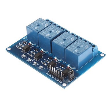
I purchased a four channel 5v relay board.The problem i am having is that i can turn on digital port and turn on relay but if i set digital port off the relay stays on..I'm pretty sure that is not in latching mode only.if disconnect the lead from the digital port the relay turns off.What am i doing wrong? User-inserted image its has 4 enable ports and vcc and ground


ARC Pro

Upgrade to ARC Pro

Subscribe to ARC Pro, and your robot will become a canvas for your imagination, limited only by your creativity.

Ireland
#1  

@rb550f Can you provide a diagram how you connect to ezb i have a similiar 8 relay card

United Kingdom
#2  

If you have it connected correctly and it isn't latching then it should turn off when you set the port to low.

Double check connections. Vcc to Vcc Ground to Ground Signal pins of Digital Ports to each of the enables

On setting of a port to on or high the relay should close. On setting the port off or low it should open. Presuming you use the normally open pin (normally closed would be the opposite).

#3  

I have d15,d16,d17,d18 connected to in1,in2,in3,in4 respectively..i have red led for 5v power on..i set each port on and i get relays green leds light and are on...when i toggle digital ports on all the relays are on.They will not toggle off unless i disconnect each digital port wires..ezb v4...common ground to relay board and ezb...

#4  

Here is how I wired a single relay unit and use the set digital on/off commands to operate and release each relay.

User-inserted image

#5  

That is basically the same setup i have except board has four 5vdc relays.I tried connecting a 5v led and i can toggle it on/off,but cannot toggle relays.They stay on once that digital port is activated.

#6  

I have Gnd connected to both VREF and Gnd. Is your board able to use the same electrical connection for Gnd?

#7  

Could be an issue with the amount of current needed to control the relay or it could be voltage. The ez-b v4 may not be driving high enough toward 5volts to control the relay. Most of these boards are set up to handle open connections on the relay control pins so they can be connected to devices like arduino whose pins come up open. This usually means they have a load resistor. Not sure how much this one draws on its enable pins, but I have seen some that require 20ma of current. As far as voltage, I haven't seen spec on low and high voltages for the control pins. EZ-B v4 high output is only 3.3volts. Your relay board may need a voltage closer to 5volts to work.

#8  

I'm using an EZB(4) but use a voltage regulator to provide +5 vdc to operate the relay.

#9  

I also use 5v reg supply separate from ezb..I dont know what relay board to use if logic high on ezb is only 3.3 v. Any suggestions would be appreciated...I will test it on my ezab 3 and see if that works..

#10  

I'm using the EZB(4) to operate 4 of these relays and they all operate using the 3.3 vdc logic high. The 5 vdc is only used to operate the relay coil.

#11  

Well relay board works on EZB v3.But not on EZB v4.What do i need to use to make it work on new EZB ?

#12  

Here is the blurb on the relays I use------------------------------ What does your data sheet say ?


This relay is designed so that the micro-controller is electrically isolated from the relay power. All the micro-controller has to do is illuminate the LED in the optocoupler. It also has the advantage of having screw terminals for all connections, no easily dislodged jumper connections.

An unusual feature of this module is the TLP290 photocoupler. It has two LEDs back to back so it doesn't matter which of the input connections is positive and which is negative. With 5V across the VREF and CH1 terminals an LED will illuminate and cause the relay to close.

The connections on the control side would be 5V DC from a power supply to DC+ and DC- and a digital high or low output from the micro-controller to the CH1 terminal. If a high output is used to energize the relay then the VREF is connected to the controller GRD terminal, and if a low output from the controller will energize the relay the VREF is connected to VCC (+5V).

On the contact side the load can be connected to the normally open (NO) or normally closed (NC) connections.

Most micro-controllers digital control pins can source an absolute maximum of 40 milliamperes (mA). And the VCC (positive voltage) and GRD (negative voltage) pins can source (positive voltage) or sink (negative voltage) 200 mA. So since 40 mA is not enough to operate most relay coils a transistor is often used to switch the current for the coil. In this case the transistor is controlled by an optocoupler. It is best to supply the relay coil power independent of the micro-controller and that is what this relay is designed for.

#13  

I think i will try to use a Logic Level Converter 3.3V to 5V TTL Level Converter Logic Bidirectional.Since the relay board works on EZB3 .This should take care of the 3.3 v logic coming from EZB4 output to control 5v logic relay board..Sorry dont have data sheet for this board.

#14  

Here is the converter i am talking about.. User-inserted image Module features:

1, 2-channel high-voltage and low-voltage logic logic bidirectional translation

2, 2-channel high-voltage logic low voltage logic converted into a one-way conversion

3, the module small, 1.5cm X 1.5cm

4, the module is compatible with the bread plate, can be directly plugged into the breadboard use

Instructions for use: [high voltage is 5V low voltage of 3.3V for example]

HV and 5V power connection

LV with 3.3V power supply connection

GND connection negative power, two power commons

RXI input 5v TTL, in RXO 3.3v TTL output

TXI input and output 3.3V TTL, TXO input and output 5V TTL, TXI and TXO bidirectional conversion

#15  

Yes, I got some similar boards from Sparkfun.com to use with the EZB(4) and the 500, 700, and 800 Roomba.

#16  

Thank you for the help.Very much appreciated onthis forum.

Ireland
#17  

@rb550f Tested 8ch card similar to yours.no problem am I correct in saying a digital " on " switches on relay but relay remains energised by digital " off " ,until you disconnect port

#18  

@Bravia, that seems correct. @rb550f cannot get the relay to release with the "digital off" command and must disconnect the port to release the relay.

Ireland
#19  

If that the case I would check the supply voltage to the relay card mine is around 5 volt and make sure both grounds are connected.

I cannot see how a digital off would give a voltage to energise relay

#20  

@rb550f do you have a link for that converter? That looks like a great way to solve my issues also.

#21  

Here is a LINK to a board that I use for converting TX, Rx levels between the EZB(4) UART0 and the Roomba R3 model TTL port.

User-inserted image

#22  

The digital outputs of the Ez-b v4 are different from the digital outputs of the ez-b v3.
according to the spec sheet ez-b v3 digital outputs are rated

Digital I/O High-Current Sink. - 25 mA Digital I/O High-Current Source - 25 mA Digital ports can output low current +5 or GND to power LED’s or communicate with peripherals.

The ez-b v4 digital outputs are rated

330 ohm current limiting Resistors on each Digital I/O pin

Digital I/O TTL Voltage Level (output) 3.3VDC

Can't find a sink and source current in the EZ-B v4 spec, but like the digital output high voltage the digital output source and sink current are probably different as well.

The ez-b v4 digital outputs are having trouble meeting the input requirements of the relay board.