PRO
rb550f
USA
Asked
— Edited
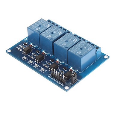
I purchased a four channel 5v relay board.The problem i am having is that i can turn on digital port and turn on relay but if i set digital port off the relay stays on..I'm pretty sure that is not in latching mode only.if disconnect the lead from the digital port the relay turns off.What am i doing wrong?

I also use 5v reg supply separate from ezb..I dont know what relay board to use if logic high on ezb is only 3.3 v. Any suggestions would be appreciated...I will test it on my ezab 3 and see if that works..
I'm using the EZB(4) to operate 4 of these relays and they all operate using the 3.3 vdc logic high. The 5 vdc is only used to operate the relay coil.
Well relay board works on EZB v3.But not on EZB v4.What do i need to use to make it work on new EZB ?
Here is the blurb on the relays I use------------------------------ What does your data sheet say ?
This relay is designed so that the micro-controller is electrically isolated from the relay power. All the micro-controller has to do is illuminate the LED in the optocoupler. It also has the advantage of having screw terminals for all connections, no easily dislodged jumper connections.
An unusual feature of this module is the TLP290 photocoupler. It has two LEDs back to back so it doesn't matter which of the input connections is positive and which is negative. With 5V across the VREF and CH1 terminals an LED will illuminate and cause the relay to close.
The connections on the control side would be 5V DC from a power supply to DC+ and DC- and a digital high or low output from the micro-controller to the CH1 terminal. If a high output is used to energize the relay then the VREF is connected to the controller GRD terminal, and if a low output from the controller will energize the relay the VREF is connected to VCC (+5V).
On the contact side the load can be connected to the normally open (NO) or normally closed (NC) connections.
Most micro-controllers digital control pins can source an absolute maximum of 40 milliamperes (mA). And the VCC (positive voltage) and GRD (negative voltage) pins can source (positive voltage) or sink (negative voltage) 200 mA. So since 40 mA is not enough to operate most relay coils a transistor is often used to switch the current for the coil. In this case the transistor is controlled by an optocoupler. It is best to supply the relay coil power independent of the micro-controller and that is what this relay is designed for.
I think i will try to use a Logic Level Converter 3.3V to 5V TTL Level Converter Logic Bidirectional.Since the relay board works on EZB3 .This should take care of the 3.3 v logic coming from EZB4 output to control 5v logic relay board..Sorry dont have data sheet for this board.
Here is the converter i am talking about..
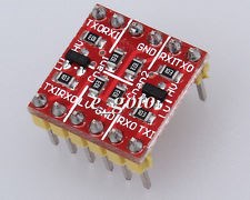
Module features:1, 2-channel high-voltage and low-voltage logic logic bidirectional translation
2, 2-channel high-voltage logic low voltage logic converted into a one-way conversion
3, the module small, 1.5cm X 1.5cm
4, the module is compatible with the bread plate, can be directly plugged into the breadboard use
Instructions for use: [high voltage is 5V low voltage of 3.3V for example]
HV and 5V power connection
LV with 3.3V power supply connection
GND connection negative power, two power commons
RXI input 5v TTL, in RXO 3.3v TTL output
TXI input and output 3.3V TTL, TXO input and output 5V TTL, TXI and TXO bidirectional conversion
Yes, I got some similar boards from Sparkfun.com to use with the EZB(4) and the 500, 700, and 800 Roomba.
Thank you for the help.Very much appreciated onthis forum.