
Ellis
4 Relay Control
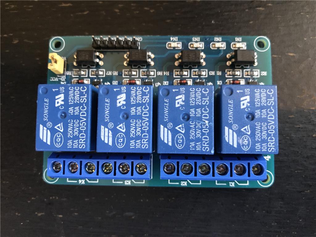
I saw on the message board that I can purchase relay boards that I can control with my Ez-Robot Micro-Controller. After a little investigation, I purchased a Four Relay Module. The manufacturer is JDtec Model # 4450182. I have included a picture so you can see it. It however did not come with a instruction manual. I am at a loss of how to install it to my micro-controller and motors.
I have a linear Action Lift that will make my robot change height when requested. The actuator has two wires and goes one way when connected to 12v DC and the other way when wires are reversed.
Can you show me how to connect the module to my ezb micro-controller and how to connect wires to make my actuator go both ways on command. I know I will need to write code to make it work. Right now I want to connect it correctly.

First of all, it is JBTek, not JDTec, so it might be easier to find a datasheet with that.
The best I found though were the review comments on Amazon.com https://www.amazon.com/JBtek-Channel-Module-Arduino-Raspberry/dp/B00KTEN3TM
You might have been better off using relays that others on the forum have used rather than going with an undocumented unknown. For instance, from the Amazon comments, it appears that this board requires a 5v power source, so to drive from an EZ-B, you are going to need a 5V regulator.
It does trigger on 3.3vDC, so once you have your board power and ground connected, you can hook up EZ-B digital pins to the 4 "INx" pins to trigger the relays. The amperage draw of the pins was measured by one of the Amazon commentators at 2.1 ma so you should be OK with that.
You hook up the device you want the relay to switch to 2 of the 3 screw terminals on each relay depending on whether you want it normally open or normally closed.
Alan
I wasn't able to tell from the brief research if these are latching or non-latching relays. For most uses, you would want latching relays so they trigger with a pulse from a digital pin, then release from another pulse. That way they aren't drawing constant current from the EZ-B power supply when in use, but depending on your application, that may not matter.
Alan
Here's a little video I made a while back that may help
Sorry couldn't read the company name on the board easily.
Thanks for your help. I am going to try this one to see if it will work. Can you tell me about where I can find sample code to make it work.
Also can you tell me about high and low on signal wiring.
The board in Jeremie's video appears to be very similar, so it can be used as a rough guide.
In the header strip with the IN1 -IN4 pins, you need to supply 5v to the VCC pin. Jeremie did this using an EZ-B 5V regulator from the power port of a digital pin.
You need to connect the ground pin on the other end of hte header to a ground pin on the EZ-B (and if you are using an alternate power source for the 5v, you need to tie your grounds together).
Then connect the signal pins of 4 EZ-B digital ports to the 4 INx pins.
Turning the pins high and low is just sending ON or OFF commands to the pins. You can do this either in scripting or using a SET Digital object.
Alan
Thanks Alan. You helped a lot.
Can you give me a sample command for Hi and Low?
Not in front of my computer for the exact syntax, but it is the set digital command. High-Set digital / port / on Low - set digital / port / off
Alan
@Ellis,
This is one of the most basic and simplest things you can code in ARC. This command relates directly to the digital ports. You should really do yourself a huge favor and take some time and read through and study the Script Help (EZ Script Functions) list inside any EZ Script control. You also should down load other people's project and EZ Robot Example projects to see how they do simple coding.
To answer your question you need to use the Set command to turn the digital port on and off. Here's the directions from the Script Help (EZ Script Functions) list I mentioned above: