USA
Asked — Edited

2.5 Amp Motor Controller.... Help!

I wired up the controller per DJ's instructions. It's getting power. The little light is on but nothing happens.

Any ideas? Troubleshooting techniques?


ARC Pro

Upgrade to ARC Pro

ARC Pro will give you immediate updates and new features needed to unleash your robot's potential!

#1  

Same here. I Just got my third one yesterday but have not tried it yet. Very strange that two don't seem to work.

#2  

Bookmaker did you order yours through EZ? I ordered mine through here. I assumed it would work no problems....

#3  

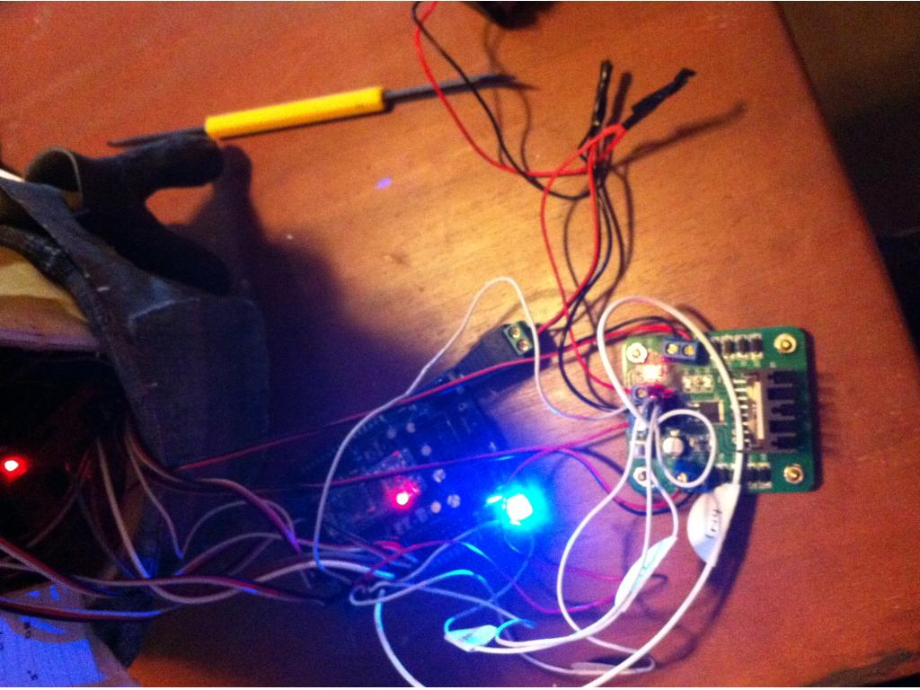
I have the EZ-B one and one form the RobotShop. The only one that works is the little postage stamp sized red one the was originally recommended by DJ. I have burned up three of those but they all worked when I hooked them up. I have tested the new ones and they are getting a signal and the boards are getting power. It really is a mystery.

#4  

Hey Sam , just double checking , did you connect your ground to the EzB and also split to directly to your power source? Also the chip that handles the business end of PWM can either take an external 5v and ground or there is the little push button , push the button and it turns the onboard 5v regulator on for the motor controllers chip and that should get you to power on. This most likely is the 5v power not being on or a grounding reference issue. I hope this fixes your problem quickly! - Josh

#5  

Hey Josh,

I have this one and followed these instructions.
2.5 Amp Controller

I didn't know it needed to be grounded to the ez-board too.

These go to the battery:

  1. Connect L298 VCC to your battery supply positive
  2. Connect L298 GND to your battery supply negative

This is connected to pin as seen here: 3) Connect L298 +5 to a +5 pin on the EZ-B (in the diagram I used +5 from Pin D0)

  1. Connect L298 IN1 to EZ-B Pin D1
  2. Connect L298 IN2 to EZ-B Pin D2
  3. Connect L298 IN3 to EZ-B Pin D3
  4. Connect L298 IN4 to EZ-B Pin D4

Then red and black for each motor go to the appropriate motors.
8) Connect L298 OUT1 to Motor 1 (Used this one for left side) 9) Connect L298 OUT2 to Motor 2 (Used this one for right side)

If you look at the picture there is a white button. I tried pushing it, no change.

Thanks for the help

Samantha

#6  

OK I was just trying to play with it again. I tried changing out the wires and I noticed when I push on the board the motors just start working.

But still when I try to use the controls nothing.

#7  

Bad connection? Yes you splice ground from your controller and it also goes to the ground on.your port . They call it a ground reference. Weird that it works when u push on it. Bad.connection maybe? It shows where to ground on the board is a different place but either way.its.just a ground.

#8  

OK playing with him now will try.

#9  

Yea the ground from port , should also be connected to.the ground on your power source. I have 4 of these controllers but I have not had and strange issues.... Yet lol

#10  

So ground that comes from the board I should put a y shape wire and connect to battery and then other to ez b?

#11  

Be sure the lil push button on the motor controller is off if your connecting the 5v to the EZ-B. I had the run away motors when it accidently got turned on.

ps Yes, put a 2nd wire in the motor controller's ground terminal, connected to a EZ-B Gnd pin.

#12  

Yes ground from ezb and also from battery

#13  

ok now attached ground to ez-b as well. Still no such luck but if I touch it (not sure how) it moves a bit.

#14  

Hmm something must be loose , a bad solder connection maybe , the fact it only works when you press on it is weird. :(

#15  

Yeah.... Poopie.... You hear it engage a bit when it's plugged in too.

#16  

I keep hopeing that you guys come up with something. I am dead in the water. Is there a way to test to see if the white switch is on or off. It dosn't seem to make any difference but I thought it would be nice to kown.

#17  

Unplug from ez-b, should still be connected to power. Push it up and down if light comes on then it's external power. Should be pushed down.

#18  

I just ran into another runaway on startup case... Seems the EZ-B leaked a lil current out a digital port on power up, just enough to trigger movement. My solution was to power up EZ-B, connect, & cycle on n off the 4 digital ports connected to my motor controller's In ports, BEFORE enabling the motor control (in my case, via 2 more digital ports connected to EnA & EnB - but waiting to apply power to the motor controller til this point should work too).

#19  

@ndavid79

cycle on n off the 4 digital ports connected to my motor controller's In ports

Huh? What do you mean cycled the ports on and off. Sorry new.

Samantha

#20  

In ARC, I added 4 "Set Digital" controls (Add Control > Digital > Set Digital) & configured them to the 4 ports connected to my motor controller... Then I clicked the red button to turn the port ON, then the green button to turn the port OFF on each of the 4 Set Digital controls.

#21  

ok.. got that. Thank you for explaining. I am new but I am semi technical and can follow directions most of the time.

Tried that still. Didn't work. But when I then tried moving the h-bridge control thing, it would turn on and off the (what I think it correct ports) by itself. Is that normal? Does make me believe it is hooked up correctly but I could be having a blonde moment. :o)

#22  

Yep, as you use the H-Bridge Movement Panel, the Set Digital controls will light up indicating what the actual ports are doing.

Can you take a picture of your motor controller & post it? Maybe we can spot something missing.

#23  

User-inserted image

Kind of hard to tell. But here you go...

#24  

Are there 2 jumpers on the 2nd row of pins behind the 4 pins that go to the EZ-B? Are the Motor out terminal blocks as crocked as they look in that pic?

#25  

Um... No jumpers. No where in the instructions did it say jumpers. Will go grab some today.

As far as terminals, this is how they came. The one moves a smidgen. The one on left by in4 in pic.

#26  

Ahh, we found The problem & another. Instead of jumpers, lets run 2 more wires to EZ-B, which will give you speed control aswell. The outer 2 pins on the 2nd row (ignore the center 2 pins) are the Enable Pins, EnA & EnB, run each to a digital port on EZ-B. In ARC, add 2 PWM Sliders (Add Control > PWM > PWM Slider) and configure them to the ports you connected EnA & EnB to. Put the 2 PWM Sliders to 75% and test your motors from the H-Bridge Movement Panel!

That terminal block that moves a smidge, most likely has a broken solder joint which will need repaired. Do you have a soldering iron by chance?

#27  

EnA & EnB: OK I will try that when I get home.

I did look at the solder and it seemed to be fine. But will double check.

I do have a solder iron. (one time I made an elven crown out of solder for halloween. It was a B%$&h to work with. The end result wasn't bad though, light weight and easily forms to the wearers head.)

Thank you... Thank you! You guys are so awesome :o)

I am bringing my Minion to Maker Faire and am hoping he'll actually be functioning.

#28  

I think that just might work. Thanks guys!

#29  

just in case..this schematic of my H bridge hookup might help.... (go to page 2 of the thread)

...This looks like the same H bridge I have in Legion...(my RAD 2.0 bot)

I have a schematic posted on how I wired my H bridge.....you do need to write a custom Movement Panel script to make this work....I can provide mine if you think that might help.

v/r

kevin

LEGION thread

#30  

@Kevin - What do you mean you need to write a customer movement panel?

After putting the two wires on EnA & EnB, the left motor works. He now goes in a circle....

#31  

sounds like you are getting it working......great! you gotta love the one legged duck syndrome! ;)

You will need to write individual scripts for each movement.... the H bridge you have is not one of the ones DJ has as part of the drop down menu....correct?......so you will need to write a short script for each movement.....then point to those scripts inside what DJ calls a movement script (panel).

You are controlling 4 things with 4 Digital Signals (your digital ports of course may be different) -motor fwd polarity -motor reverse polarity -turn on right motor -turn on left motor

here is how it works don't freak out if this does not make sense to start ;)

Create Custom EZB script: Add Control/Scripting/EZ Script

Turn Right set(d18,off) ;Comment...Set left motor to Reverse set(d8,on) ;Comment....Set Right motor to forward set(d19,on);Comment....Turn on Left motor set(d9,on); Comment...Turn on Right motor sleep(1000) ;Comment....this turns the bot to the right for 1 second (you can make it longer) set(d19,off) ;Comment...Stop Left Motor set(d9,off) ; Comment....Stop Right Motor

Turn Left set(d18,on) set(d8,off) set(d19,on) set(d9,on) sleep(1000) ;Comment...this turns the bot to the left for 1 second set(d19,off) set(d9,off)

Move Forward set(d18,off) ;Comment...turn right motor to forward set(d8,off) ; Comment...turn left motor to forward set(d19,on); Comment....turn on left motor set(d9,on); Comment turn on right motor

sleep(2000) ; comment...optional....depending on how you want to control your bot.......

set(d19,off)

set(d9,off)

Move Backward set(d18,on) set(d8,on) set(d19,on) set(d9,on) sleep(1000) set(d19,off) set(d9,off)

Now you need to create a Movement Script that will launch the Forward/Backward/Left/Right scripts

Movement Script (from the pull down...Add Control/Scripting/Movement Script) ControlCommand("Stop",scriptstart) ControlCommand("Forward",scriptstart) ControlCommand("Turn Right,scriptstart) ControlCommand("Turn Left,scriptstart)

We will help you with this........it is not too bad once you get the hang of it... as they say in Horton Hears a Who......we are here!

v/r

kevin

#32  

Progress, Yay! The 2 connections on the lose screw terminals prolly just needs reflowed... That means touching a hot soldering iron to the joints on the bottom of the board, briefly reliquifing the solder already there.

#33  

Hahaha... yes we already established that. I just finished doing that and testing it.

Woo hoo............ After fixing the solder on the one blue thingy... I have movement.

#34  

Sweat!

@kkeast, the board she has is a clone of the 4-Wire Hbridge, which ARC has a Movement Panel for drive motors anyway.

#35  

@Kevin - I just saw the script thing. I will have to figure that out. DJ has made it pretty simple and I think I'll be able to do it. :o) We will see.

I bought my board from here so I followed those instructions...

I just drove him around. He's a bit top heavy but I just finished the final wiring.

Still need to work on his hands, the ones he has are really too heavy.

Will have to work on a little video tomorrow so everyone can see him.

And now thanks to everyone's help, he wont embarrass himself when he visits DJ's booth at Maker Faire.

#36  

You will not a move script...which is nice...since you got the board from DJ can't wait to see your video!