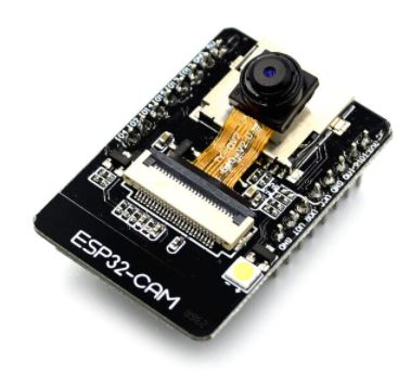
ESP32 Cam With PCA9685 Firmware

Synthiam ARC ESP32-CAM firmware: EZ-B-compatible controller, OV2640 live video, PCA9685 16-channel servo/PWM, stable timing and AP/Client Wi-Fi

Compatible Hardware

ESP32 Cam by Espressif
ESP32-CAM as an EZB for Synthiam ARC: stream video, control GPIO/servos, AP/Client WiFi, and ARC D0-D23 to GPIO pin mapping.
Wi-Fi
Servos Varies
Camera
Audio
UART Varies
I2C
ADC Varies
Digital Varies

Description

This firmware converts a ESP32 Cam into an EZB for ARC to connect to it.

This firmware turns an ESP32-CAM into a Wi-Fi EZB-compatible controller that can run Synthiam ARC peripheral control and drive up to 16 PWM/servo channels through an attached PCA9685 breakout board - while still supporting live camera streaming from the onboard OV2640.

It’s designed for robots that need vision + 16 servo outputs without upgrading to a larger controller board.


What the Firmware Provides

  1. EZB Compatibility (Peripheral Controller) The ESP32 accepts ARC control commands and behaves like an EZB-compatible controller for common robotics tasks such as:
  • servo position commands
  • PWM output control
  • digital on/off ports
  • UART expansion passthrough (Serial2)

ARC can connect and send commands exactly like it would to an EZB style controller.

  1. Integrated Camera Streaming The firmware initializes the ESP32 camera driver and streams JPEG frames to ARC over a dedicated TCP connection. This provides live video feedback in ARC while the controller side remains responsive.

  2. PCA9685 Expansion for 16 Channels Instead of using ESP32 GPIO for servo timing, this firmware uses an Adafruit PCA9685 PWM servo Driver over I2C. That means:

  • ARC ports D0 to D15 map directly to PCA channels 0 to 15
  • servo timing stays stable even while Wi-Fi and camera streaming are active
  • you get more usable servo outputs than most ESP32-CAM boards can provide natively
  1. Simultaneous Operation Camera streaming and EZB command handling run side-by-side. The ESP32 can:
  • stream video continuously
  • accept and execute servo/digital/PWM commands
  • keep TCP connections alive for both ARC control + camera streaming

Required Hardware

To use the expanded servo/digital output capability, you’ll need:

  • an ESP32 camera module supported by the firmware
  • a PCA9685 board (commonly the Adafruit-compatible 16-channel PWM driver)

The PCA9685’s servo power rail is not intended to be powered by the ESP32-CAM. Use a dedicated servo supply and share ground.


Supported ESP32 Camera Boards

This firmware includes camera model pin maps for many ESP32 camera variants, including:

  • CAMERA_MODEL_AI_THINKER
  • CAMERA_MODEL_WROVER_KIT
  • CAMERA_MODEL_ESP_EYE
  • CAMERA_MODEL_M5STACK_PSRAM
  • CAMERA_MODEL_M5STACK_V2_PSRAM
  • CAMERA_MODEL_M5STACK_WIDE
  • CAMERA_MODEL_M5STACK_ESP32CAM
  • CAMERA_MODEL_M5STACK_UNITCAM
  • CAMERA_MODEL_M5STACK_CAMS3_UNIT
  • CAMERA_MODEL_TTGO_T_JOURNAL
  • CAMERA_MODEL_XIAO_ESP32S3
  • CAMERA_MODEL_ESP32_CAM_BOARD
  • CAMERA_MODEL_ESP32S3_CAM_LCD
  • CAMERA_MODEL_ESP32S2_CAM_BOARD
  • CAMERA_MODEL_ESP32S3_EYE
  • CAMERA_MODEL_DFRobot_FireBeetle2_ESP32S3
  • CAMERA_MODEL_DFRobot_Romeo_ESP32S3

Only enable one camera model at a time. A mismatched model typically causes camera init failures or empty frames.


How ARC Port Mapping Works in This Firmware

This firmware’s "mapping" is intentionally simple and consistent:

PCA Channels

  • ARC ports D0 to D15 map to PCA9685 channels 0 to 15

  • these channels can be treated as:

    • servos (position 0 - 180)
    • PWM percent (0 - 100)
    • digital on/off (full off / full on)
  • digital ports are write only. The read option will simply read the cached value of the last state. This is a limitation of the PCA9685.

Because PCA9685 is external hardware, you don’t need to fight ESP32-CAM GPIO limitations to get stable outputs.

ADC Inputs

ADC reads are currently stubbed (returns 0) in the shown firmware due to the PCA9685 not having ADC input pins. It is a write-only PWM module.


Network Behavior

The firmware runs two TCP servers:

  • Port 23: EZB compatible command/control channel
  • Port 24: camera JPEG streaming channel

It also supports two Wi-Fi modes:

Access Point Mode (default in the sample)

  • ESP32 creates its own Wi-Fi AP (ex: GetOffMyLawn)
  • default IP is 192.168.1.1
  • easiest for direct robot setup with no router required

Client Mode

  • ESP32 connects to an existing Wi-Fi network
  • the device IP is shown in Serial output
  • useful for robots on a larger LAN

Camera Compression Auto-Management

The ESP32-CAM has limited buffer space for image payloads. This firmware includes optional dynamic JPEG compression tuning:

  • checks frame sizes over a window of frames
  • adjusts JPEG quality to keep frames within a target range
  • reduces stalls and helps keep streaming smooth

This is especially useful when lighting changes cause frame size spikes.


Benefits of This Firmware

More servo Outputs PCA9685 provides 16 stable PWM/servo channels without relying on ESP32 PWM timers.

Stable Timing While Streaming Servo timing is offloaded to PCA hardware, so video streaming doesn’t wreck servo pulses.

All-in-One Robot Board You get camera, control, and servo expansion in one compact setup.

Simple ARC Port Model ARC sees consistent channels (0-15) that don’t change per the ESP32-CAM board layout.

Great Fit for Servo-Heavy Robots Robotic heads, arms, animatronics, pan/tilt rigs, hexapods, and any build where ESP32 pins alone aren’t enough.


Typical Use Cases

Perfect for robotics projects that need both vision and many outputs:

  • humanoid heads with multiple facial servos
  • pan/tilt + arm systems
  • animatronic creatures
  • camera rovers with extra actuators
  • inspection bots with a camera + servo tools

Summary

This firmware converts an ESP32 camera module into a Synthiam ARC compatible EZB style controller with:

  • live OV2640 camera streaming over TCP
  • EZB compatible control channel for ARC commands
  • 16-channel PCA9685 servo/PWM expansion
  • AP or Client Wi-Fi operation
  • optional auto JPEG compression adjustment for stable streaming

To deploy successfully:

  1. Select the correct CAMERA_MODEL_* define
  2. Set your Wi-Fi mode (AP or Client)
  3. Wire the PCA9685 to the configured SDA/SCL pins and confirm the address
  4. Flash the firmware and connect from ARC (camera + controller)

Downloads

Download
  • Added ARC EZ-B discovery broadcast (UDP 4242)

    • ESP32 firmware now broadcasts discovery packets compatible with ARC’s "EZ-B Scan" feature.
    • Broadcast format matches ARC desktop scanner.
  • Automatic network broadcast every 5 seconds

    • Allows ARC to discover the ESP32 EZ-B without manual IP entry.
    • Works continuously, even when no ARC client is connected.
  • Supports both AP mode and Client mode

    • AP mode uses fixed broadcast address 192.168.1.255
    • Client mode dynamically calculates broadcast address from subnet mask.
  • Unique device naming

    • Device name is specified by user configuration section.

Performance & Stability

  • Non-blocking broadcast timer

    • Broadcast scheduling uses millis() with rollover-safe arithmetic.
    • No blocking delays added to the main control loop.
  • Broadcast continues during active ARC connections

    • Discovery remains visible even while the controller is in use.

Implementation Details

  • Added UDP broadcast support using WiFiUDP.

Tested Scenarios

  • ARC device discovery in:

    • ESP32 AP Mode
    • ESP32 Client Mode (connected to router)
  • Multiple ESP32 devices broadcasting simultaneously.

  • Continuous ARC connections while broadcasting.

Click to show supported capabilities
Supported Capabilities
  • Broadcasts to ARC's PnP network scanner
    Controller broadcasts itself on the network using the ARC PnP network scanner protocol. This is so ARC can find devices on the network which may have dhcp assigned addresses.
  • Can stream video v4 codec
    The controller supports the streaming Video v4 codec on a TCP or UART or USB connection.
  • Hardware UART TX/RX with DMA buffer and adjustable baud rate
    Contains 1 or more hardware UARTs with TX/RX functionality and DMA RX buffering.
  • Native WiFi Connectivity from ARC
    Controller supports WiFi connectivity using TCP between your computer with ARC.
  • PWM Duty on digital ports
    Digital ports can output a PWM between 0% and 100%.
  • PWM servos on digital ports
    The controller supports PWM Servos on digital ports. These are also called Hobby servos.
  • PWM servos on digital ports can release their position
    PWM servo driver on digital ports support the feature to release their holding position.
  • Read/Write Digital I/O Ports
    The ports marked as being digital will respond to Read and Write commands of boolean logic. The status of the digital port will be either TRUE or FALSE when voltage is detected or not, respectively.
Download

In addition to the previous configuration release notes, this firmware update includes an EZB broadcast. In ARC, you can now see the IP address broadcast directly in the ARC connection robot skill's IP address dropdown.

Click to show supported capabilities
Supported Capabilities
  • Broadcasts to ARC's PnP network scanner
    Controller broadcasts itself on the network using the ARC PnP network scanner protocol. This is so ARC can find devices on the network which may have dhcp assigned addresses.
  • Can stream video v4 codec
    The controller supports the streaming Video v4 codec on a TCP or UART or USB connection.
  • Hardware UART TX/RX with DMA buffer and adjustable baud rate
    Contains 1 or more hardware UARTs with TX/RX functionality and DMA RX buffering.
  • Native WiFi Connectivity from ARC
    Controller supports WiFi connectivity using TCP between your computer with ARC.
  • PWM Duty on digital ports
    Digital ports can output a PWM between 0% and 100%.
  • PWM servos on digital ports
    The controller supports PWM Servos on digital ports. These are also called Hobby servos.
  • PWM servos on digital ports can release their position
    PWM servo driver on digital ports support the feature to release their holding position.
  • Read/Write Digital I/O Ports
    The ports marked as being digital will respond to Read and Write commands of boolean logic. The status of the digital port will be either TRUE or FALSE when voltage is detected or not, respectively.
Download

*Note: This firmware (v2) or newer requires ARC 2026.02.02.00 or newer

ARC can send extremely small packets (sometimes 1-2 bytes) very quickly. To prevent WiFi/TCP receive window stalls, the firmware:

  • Aggressively drains incoming TCP data into a ring buffer
  • Parses commands from the ring buffer (not directly from the socket)
  • If the ring buffer fills, it drops the oldest bytes so the socket stays drained (favoring "latest commands" over stale backlog)

Dual-task architecture (camera + controller)

The firmware runs two FreeRTOS tasks:

  • EZB Task (higher priority): keeps command latency low and prevents TCP stalls
  • Camera Task (lower priority): captures and streams frames continuously

This keeps camera streaming from interfering with control responsiveness.


User Settings to Configure in the Firmware

A) Select your camera model

In the Camera Settings section, uncomment exactly one camera model:

// #define CAMERA_MODEL_AI_THINKER
// #define CAMERA_MODEL_WROVER_KIT
// ...

If the camera model is wrong, the camera will fail to initialize and you’ll see the reason in the Serial Monitor.


B) Set camera clock frequency (if needed)

Default is recommended:

#define XCLOCK_FREQUENCY 20000000

If you get unstable video, frame failures, or camera init problems (often caused by noise/long ribbon cable/power issues), try:

//#define XCLOCK_FREQUENCY 10000000

C) Choose WiFi mode (Access Point or Client)

Access Point Mode (default in this firmware)

Uncomment:

#define AP_MODE

Then set your AP SSID/password:

#define WIFI_AP_SSID "GetOffMyLawn"
#define WIFI_AP_PWD  ""
  • In AP mode, the ESP32 creates its own WiFi network.
  • The firmware configures the AP IP as 192.168.1.1.

Client Mode (connect to your router)

Comment out #define AP_MODE and set:

#define WIFI_CLIENT_SSID "My Network"
#define WIFI_CLIENT_PWD  "My Password"

In Client Mode, the ESP32 prints its assigned IP address in the Serial Monitor after it connects.


D) PCA9685 I2C pin selection (ESP32 GPIO)

These define which ESP32 pins are used for I2C to the PCA9685:

#define PCA_SDA_PORT 14
#define PCA_SCL_PORT 15

Important:

  • Pick pins that are actually broken out on your ESP32 board.
  • Avoid camera pin conflicts (the firmware checks this and will stop with a clear fatal error message if you pick a conflicting pin).

E) PCA9685 I2C address

Most boards use the default address:

#define PCA9685_ADDR 0x40

If you changed A0-A5 solder jumpers on the PCA9685 board, update this to match.


F) I2C speed (noise tolerance)

Default is fast:

#define I2C_SPEED 400000

If you have long wiring or electrical noise (servos jittering, PCA not detected, intermittent control), drop to 100kHz:

#define I2C_SPEED 100000

G) PWM frequency (servos vs LEDs)

Standard analog servo PWM is:

#define PCA_PWM_FREQUENCY_HZ 50

Leave this at 50Hz for servos. (Higher frequencies are not suitable for servo timing unless you redesign the servo pulse logic.)


H) servo pulse range (endpoints)

These define the servo pulse width limits:

#define SERVO_MIN_US 500
#define SERVO_MAX_US 2500

If your servo endpoints need tuning, adjust these values. Keep ranges conservative to avoid binding/overdriving servos.


I) Auto compression (ACOMP) for camera streaming

The ESP32-CAM has tight memory limits for buffering. With ACOMP enabled, the firmware dynamically adjusts JPEG quality to keep frame sizes in a target range and reduce dropped frames.

Enabled:

#define ACOMP

Key settings:

  • COMP = starting compression/quality value (lower = higher quality, larger frames)
  • ACOMPSTEP = how fast quality changes
  • ACOMPFRAMECNT = how many frames are averaged before adjusting (higher reduces visible "quality flicker")

Wiring: Connecting PCA9685 to the ESP32 (I2C)

The PCA9685 uses I2C, which is a 2-wire data bus plus power and ground.

Required wires

Connect:

  1. ESP32 GPIO SDA (PCA_SDA_PORT) PCA9685 SDA
  2. ESP32 GPIO SCL (PCA_SCL_PORT) PCA9685 SCL
  3. ESP32 GND PCA9685 GND (must share ground)
  4. PCA9685 VCC (logic) ESP32 3.3V (recommended for I2C logic compatibility)

Servo power (separate from logic power)

Most PCA9685 boards have a separate V+ terminal block for servo power.

  • Power servos from an appropriate external 5V supply (or whatever your servos require).
  • Do not power servos from the ESP32 3.3V regulator.
  • Always connect the servo power ground to the ESP32 ground so signals reference correctly.

Summary:

  • ESP32 3.3V PCA VCC (logic)
  • External 5V PCA V+ (servos)
  • Grounds all tied together

Serial Monitor: Watch for Errors (Very Important)

Set Serial Monitor to:

  • 115200 baud

The Serial output is your "first stop" for diagnosing setup issues. This firmware prints clear messages for:

Camera issues

  • Wrong camera model define
  • Camera init failure codes
  • Frame capture failures
  • Suggestions like lowering XCLK frequency

PCA9685 issues

At startup the firmware probes the PCA9685 address. If it does not ACK, it prints a repeating message showing:

  • SDA GPIO
  • SCL GPIO
  • I2C address
  • Reminder to check wiring, jumpers, power, and ground

It will not proceed until the PCA9685 is detected (so you don’t get "silent failures" later).

Pin conflicts

If your chosen I2C pins collide with camera pins, the firmware enters a fatal error loop and prints exactly what to change.


Network Ports Used by ARC

  • TCP 23: EZ-B command/control connection (servos, digital, PWM, etc.)
  • TCP 24: Camera streaming connection

If you’re troubleshooting connectivity, confirm your PC/mobile device can reach the ESP32 IP and those ports are accessible on your network.


Tips and Best Practices

  • Power matters: camera + WiFi + servos can cause brownouts if power is marginal. Use a stable power source for the ESP32 and a separate adequate supply for servos.
  • Shorter I2C wires = fewer problems: keep SDA/SCL wiring short and away from servo power wiring.
  • If PCA9685 isn’t detected: start with 100kHz I2C speed and verify grounds are shared.
  • If video stutters or fails: try lowering XCLK, lowering frame size, or increasing compression (higher compression value = smaller frames).

What You Need in Synthiam ARC

In ARC, you will typically:

  • Connect to the controller using the ESP32’s IP address (EZ-B compatible connection)
  • Add/configure the Camera device/skill to connect to the camera stream

Use the Serial Monitor output to confirm:

  • WiFi mode/IP address
  • Camera initialized successfully
  • PCA9685 detected and initialized
Click to show supported capabilities
Supported Capabilities
  • Can stream video v4 codec
    The controller supports the streaming Video v4 codec on a TCP or UART or USB connection.
  • Hardware UART TX/RX with DMA buffer and adjustable baud rate
    Contains 1 or more hardware UARTs with TX/RX functionality and DMA RX buffering.
  • Native WiFi Connectivity from ARC
    Controller supports WiFi connectivity using TCP between your computer with ARC.
  • PWM Duty on digital ports
    Digital ports can output a PWM between 0% and 100%.
  • PWM servos on digital ports
    The controller supports PWM Servos on digital ports. These are also called Hobby servos.
  • PWM servos on digital ports can release their position
    PWM servo driver on digital ports support the feature to release their holding position.
  • Read/Write Digital I/O Ports
    The ports marked as being digital will respond to Read and Write commands of boolean logic. The status of the digital port will be either TRUE or FALSE when voltage is detected or not, respectively.
Download

1) What You Need

Hardware

  • ESP32 camera board (one of the supported CAMERA_MODEL_* boards)
  • PCA9685 16-channel PWM/Servo driver board (Adafruit-compatible)
  • Jumper wires
  • Servo power supply (recommended: 5-6V, adequate current for your servos)
  • Common ground between servo power, PCA9685, and ESP32

Software

  • Arduino IDE (or compatible build environment) (Set serial monitor to 115,200)
  • Board package: ESP32 by Espressif Systems v3.3.5
  • Library: Adafruit PWM servo Driver Library v3.0.2
  • This firmware sketch ZIP package

2) Choose the Correct Camera Model

In the firmware, locate the camera model section and uncomment exactly one line:

// #define CAMERA_MODEL_AI_THINKER
// #define CAMERA_MODEL_WROVER_KIT
// ...

Important

  • Only one model should be enabled.
  • A wrong model usually causes an error in the serial monitor

3) Configure Wi-Fi Mode

Access Point Mode (default)

AP mode creates a Wi-Fi network hosted by the ESP32.

#define AP_MODE
#define WIFI_AP_SSID "GetOffMyLawn"
#define WIFI_AP_PWD  ""
  • ESP32 AP IP is typically 192.168.1.1
  • You connect your PC to this SSID, then ARC connects to the ESP32’s IP.

Client Mode

Client mode joins your existing Wi-Fi network.

// #define AP_MODE  // comment out AP_MODE
#define WIFI_CLIENT_SSID "My Network"
#define WIFI_CLIENT_PWD  "My Password"
  • Serial Monitor prints the assigned IP address once connected.

4) Wire the PCA9685 to the ESP32-CAM

The firmware uses these defines:

#define PCA_SDA_PORT 14
#define PCA_SCL_PORT 15
#define PCA9685_ADDR 0x40

Typical wiring

  • ESP32 GPIO 14 PCA9685 SDA

  • ESP32 GPIO 15 PCA9685 SCL

  • ESP32 GND PCA9685 GND

  • PCA9685 VCC 3.3V (logic power) or 5V depending on your PCA board design

    • Most PCA9685 boards accept 3.3V logic fine.
  • Servo power:

    • Use the PCA9685 servo power input (often labeled V+) with a separate 5-6V supply
    • Share ground: servo supply GND must connect to ESP32 GND / PCA GND.

PCA9685 address

Default is 0x40. If you changed address jumpers (A0-A5), update:

#define PCA9685_ADDR 0x40

5) Check for Pin Conflicts (Camera vs I2C)

ESP32-CAM boards often consume many GPIO pins for the camera bus. The serial monitor will present an error if there is a conflict. If your chosen PCA_SDA_PORT or PCA_SCL_PORT conflicts with a camera pin, the firmware will print an error repeatedly and halt.

If this happens:

  • Change PCA_SDA_PORT / PCA_SCL_PORT to pins that exist on your board and are not used by the camera.

6) Compile & Upload

Arduino IDE settings (typical)

  • Board: select the correct ESP32 board profile for your module (AI Thinker ESP32-CAM / ESP32 Wrover / ESP32-S3 etc.)
  • Flash Frequency: default/auto is fine
  • Partition scheme: default is usually fine unless you add extra features
  • Serial monitor: 115200

Upload the firmware, then open Serial Monitor.


7) Verify Startup in Serial Monitor

On boot, you should see messages similar to:

  • camera initialized successfully
  • Wi-Fi mode started (AP or client)
  • server started and waiting for client
  • PCA9685 initialized (if your firmware includes the probe / init logs)

If the PCA9685 is missing/wrong address/miswired, the firmware may:

  • print an error forever (if you enabled the I2C probe + fatal loop)
  • or appear to run but servo outputs won’t work

8) Connect From Synthiam ARC

This firmware presents two network services:

  • EZB/Controller Server: TCP port 23
  • Camera Streaming Server: TCP port 24

A) Connect as a Controller (EZB style)

In ARC:

  1. Add a connection to the ESP32’s IP address
  2. Use Port 23
  3. Connect

You should see the firmware accept the client and print:

  • "Client ezb connected from "

B) Connect the Camera Device

In ARC:

  1. Add the Camera Device / camera streaming connection (whatever your ARC workflow is for this ESP32-CAM stream)
  2. Use the same ESP32 IP
  3. Use Port 24
  4. Start the camera device

You should see:

  • "Client cam connected from "

9) Understanding ARC Port Mapping (PCA9685)

This firmware treats PCA9685 channels as ARC ports:

  • ARC Port 0 PCA Channel 0
  • ARC Port 1 PCA Channel 1
  • ARC Port 15 PCA Channel 15

Servo behavior

  • ARC servo position commands map to PCA servo pulses
  • A position of 0 is treated as "release/detach" (turn off PWM on that channel)

Digital behavior

Digital on/off uses PCA "full on" / "full off" behavior.


10) Common Troubleshooting

Camera won’t initialize

Symptoms:

  • esp_camera_init() error printed

    Fix:

  • Ensure you selected the correct CAMERA_MODEL_*

  • Reseat camera ribbon cable

  • Try lowering:

    //#define XCLOCK_FREQUENCY 20000000
    #define XCLOCK_FREQUENCY 10000000
    

PCA9685 not detected / servos don’t move

Check:

  • SDA/SCL wiring
  • Address (0x40 unless changed)
  • PCA power and shared ground
  • Servo power supply is connected and sufficient current

AP mode connects but ARC can’t reach it

Check:

  • Your PC is connected to the ESP32 SSID (not your home Wi-Fi)
  • Use IP 192.168.1.1 (typical AP config in this firmware)

Client mode keeps rebooting

This firmware restarts if Wi-Fi drops in client mode:

if (WiFi.status() != WL_CONNECTED)
  ESP.restart();

If your Wi-Fi is unstable, consider AP mode for testing.


  1. Flash firmware
  2. Open Serial Monitor @115200
  3. Confirm camera init success
  4. Confirm Wi-Fi starts and prints IP
  5. Connect ARC controller to port 23
  6. Connect ARC camera stream to port 24
  7. Send a servo command to port 0 and confirm motion

12) Safety Notes

  • Don’t power servos from the ESP32 board.
  • Always share ground between ESP32, PCA9685, and servo power.
  • Start with conservative servo endpoints (SERVO_MIN_US / SERVO_MAX_US) and adjust only if needed.
Click to show supported capabilities
Supported Capabilities
  • Can stream video v4 codec
    The controller supports the streaming Video v4 codec on a TCP or UART or USB connection.
  • Hardware UART TX/RX with DMA buffer and adjustable baud rate
    Contains 1 or more hardware UARTs with TX/RX functionality and DMA RX buffering.
  • Native WiFi Connectivity from ARC
    Controller supports WiFi connectivity using TCP between your computer with ARC.
  • PWM Duty on digital ports
    Digital ports can output a PWM between 0% and 100%.
  • PWM servos on digital ports
    The controller supports PWM Servos on digital ports. These are also called Hobby servos.
  • PWM servos on digital ports can release their position
    PWM servo driver on digital ports support the feature to release their holding position.
  • Read/Write Digital I/O Ports
    The ports marked as being digital will respond to Read and Write commands of boolean logic. The status of the digital port will be either TRUE or FALSE when voltage is detected or not, respectively.

ARC Pro

Upgrade to ARC Pro

Stay on the cutting edge of robotics with ARC Pro, guaranteeing that your robot is always ahead of the game.