Jaychadw
United Kingdom
Asked
— Edited
Hi
Successfully integrated EZ with my unity project yesterday. But now I have an issue. I am getting a compass module in the next few days and an accelerometer. I wondered if someone could explain, simply, how to connect them both up via i2c .
I've read the articles but just wanted someone to clarify it for me
Thank you

Piggyback/daisychain them. Basically connect the second I2C device to the first I2C device's pins.
What I've done with Melvin is made a small I2C Header board. It's a piece of strip board, 4 wide by however long you need (I think mine is 6 long). This plugs in to the I2C header on the EZ-B and from that I plug the I2C devices into the board.
If your devices draw a lot of current you may want to supply the power from another source than the I2C header, it'll all work provided the SDA and SCL are all joined together like this;
One of those sound use full. May I ask how you made it?
A small piece of strip board 25x64 stripboard
Trim it down to 4 strips wide, however long you need.
Pin headers check it, I rushed to find the link
Solder these in all holes.
Use jumper cables to connect from I2C on the EZ-B to the board, use jumper cables to connect devices to the board.
I'll do some pictures later when I have time if you can't figure out the above.
awesome thanks Rich that's great
A simple board. Basically, stripboard to link pin headers, join everything up with jumpers.
The 4 pins on the left connect to the I2C header of the EZ-B. The 8 rows of 4 pins on the right connect to the I2C devices.
It could be done (with a bit of jiggling around) so the board plugs directly in to the I2C header of the EZ-B since they both have 0.1" spacing.
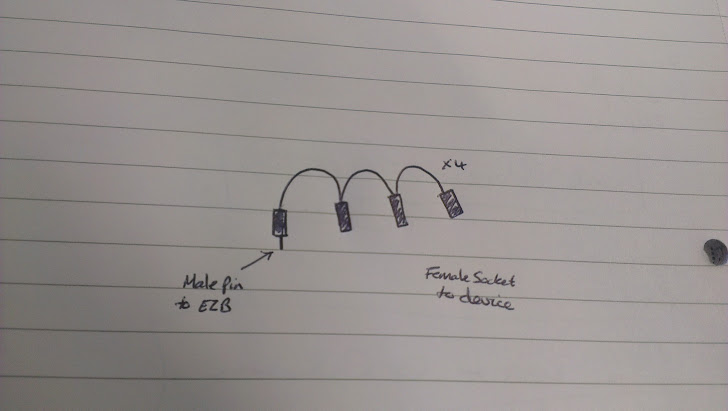
The alternative is to make up cables like this,

Male pin to plug in to the I2C header on the EZ-B, female sockets with wire looping in and out to the next.ah I see. not how I thought it worked. simpler. cheers bruv