
steve.neal
Australia
Asked
— Edited
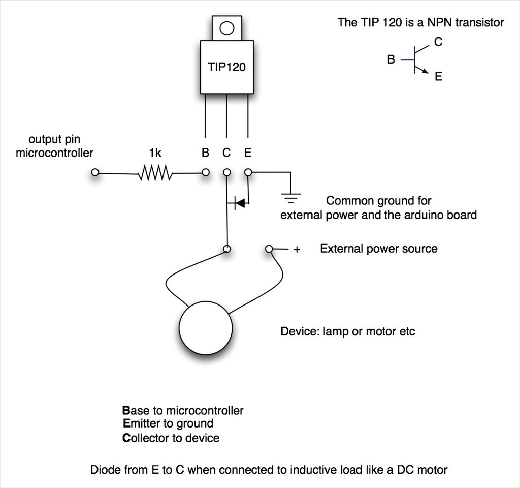
Tip120 & Tip122 Transistor Switching Circuit
I want to make some the switching circuits as per the attached picture to control some small motors and due to my limited knowledge regarding electronics, I just want to confirm the value of the resistor from the micro-controller, EZB4 in my case. Is 1K OK?
Thanks in advance
Steve

Here's a good discussion on the TIP circuit.
I believe the resistor needs changing for the V4 though as the voltage is lower (3.3v), It was a discussion between Dave and Jeremie I just can't remember which topic it was in.
Hi @Steve, What Rich is referring to is the High side switching circuit I was using to turning on and off my Sabertooth because the attached battery was keeping it "Awake" when I powered down the switching power supply that I use to power my B9. The battery is there because the Sabertooth needs a place to dump the regenerative power it makes so it won't knock off or damage the switching power supply. I think you and I had a conversation about this circuit. Anyway, when I first designed this circuit I was using a V3 EZB and had a 33k resistor between the EZB signal pin and the first transistor in the circuit. The old EZB v3 sent 5vdc through the signal port as a trigger. The New V4 EZB only sends 3.3 so the 33k resistor was too large. I had to knock that resistor down to 10K for the 3.3vdc signal voltage to pass through. At the time I was told that I could even have gone down to a 1K resistor but from my experience I learned to keep a my tolerances close for a margin of safety. Right or wrong, I use the largest resistor I can and still have the circuit work.
Anyway, the TIP circuit you're asking about is not the same thing. It's a simple low side switching circuit and is a great way to turn on and off small motors, sensors or lights. Personally, in this circuit make sure you have a transistor that will handle the amps your motor will pull. Both the TIP 120 & 122 will carry 5 amps. If you need something larger than that then considder useing a IRL3103PBF Mosfet. It will carry over 45 amps. See Riches link above. Again, I'd start using a 10K resistor where shown in your drawing above and go down from there if your circuit wont turn on.
On a different but somewhat related subject; I know you were asking about the regen properties of the Sabertooth and how to handle that with a power supply. As I stated then and again above you need a battery to dump the extra power into, thus why I designed the circuit I mentioned above. Well, Dimension Engineering has developed a new Sabertooth 2x32 that doesn't need a battery to dump the regen power into! It has an extra set of power out ports where you can simply run a proper sized power resistor between it and the main power input and use this as a Voltage Clamp. This eliminates the need and complexity of adding a dump battery and the circuit I designed I mentioned above. I have two of these units while using a 96 watt power resistor bank, I can run without a dump battery and my 30 amp power supply wont shut down! Here's the link:
Sabertooth 33x2
Here's what the Voltage clamp looks like:
Hope this helps!
Hi Dave,
Thanks for all the info regarding the TIP circuit As it turns out, I spent yesterday making a couple of the Sabertooth switching circuits from your diagram you gave me a couple of weeks ago as I have two 2x12 Sabertooths and Kangaroos.
I haven't done any electronic "kit" building for a long time, since I was a teenager, took me ages to nut out how to convert your diagram into a configuration that will work on a strip board. I wanted to keep it as small as I could. The 6 amps diodes take up heaps of room. I ended up with something I'm pretty happy with but I haven't had a chance to test them yet.
These new 2v32 Sabertooths sound pretty sweet. I'm very tempted to upgrade to avoid using a dump battery all together. Any one want to buy a couple of 2x12 Sabertooths? Are the new 2x32 Sabertooths still compatible with a kangaroo? If so I think I will upgrade, pity I wont need the new switching circuits I just made tired Story of my life
Thanks for everything Dave
Steve
That's an AWESOME work of art! very neat and well constructed. It looks a LOT better than my attempt at hobby level electronic board construction. I'd love to see the back of the board.
The main reason I had to upgrade to the 2x32 sabretooth was because the new AME 226 series arm elbow motor I'm trying to control pulls over 35 amps when it changes direction at full speed and often tops 28 amps when lifting the full load of my arm. I was getting power brown outs with the 12 amp power supply and the 2x12 Sabertooth I was using. I upgraded to the 2x32 and a 30 amp power supply. However I still get a flicker on the 2x32 Sabretooth's error light when doing an Auto Tune at full speed with this setup. This means my power supply is still under the required amp load at full speed and load. This make it hard to get a successful auto tune as it stops and returns an error. But, I'll never run my arms at full speed as it's way too fast, dangerous and a totally unnatural speed. Besides when I run at full speed I also destroy the aluminum hub, motor shaft and break the roll pin and set screws holding it all together. I need to find a good steel or Stainless Steel motor hub that can fit on a 10 mm or 11 mm motor shaft.
My advice is to hang onto your sweet little board and 2x12 sabertooth till you get everything running stably like you want. Then dump your extra components. Who knows, you may want to use it somewhere else in the robot. I have one running the radar section with a Pot as feedback to an attached Kangaroo x2.
;)
Thanks Dave , that means the world coming from you Here's the back
Your right, I need to get everything up and running first... PS. I cant wait to see your B9 arms up and running. Your robot blows my mind!
Wow, that's a fantastic planning, layout and soldering job. It was a challenge for me to lay out my board. You really make it look simple.
Thanks for the kind words about my B9. I cant wait to get my arms working either. I'm at the point that I'm confident I have the control, strength and size correct and now have them working pretty good. I just need to find a strong enough hub that connects to my motor shaft that will stand up to the torque and last. I may have to have them made out of steel somehow.
Hi Dave,
I have been thinking about the issue of a strong enough hub for your B9 arm motors. You probably have already thought of this but I thought a steel sprocket with a matching bore to the motor shaft may do the trick. Obviously you would have to drill and tap holes to mount the hardware to it but I'm sure that's well within your capability.
I found this one on Amazon. They are a little pricey though, but its a starting point. You may well find one better suited to your needs
https://www.amazon.com/Ametric%C2%AE-ISO-Sprocket-02B17-11-No/dp/B00GIZIBL6
Not sure if this sprocket has two set screws or not, as the motor shaft has two flat sides according to the data sheet.
Hope this helps
Steve
Steve, Thanks! That great! I had been thinking I could use a sprocket but had no idea where to find one. Where else but Ebay! I'm going to probably get one to see if it will work.
In the mean time I found a Stainless Steel hub that will work at The Robot Shop made by Nexus Robots and placed an order. They showed out of Stock but The Robot Shop checked with Nexus in China and they had a limited amount in stock there. They should be here in a few weeks.
www.robotshop.com/en/10mm-set-screw-key-hub.html