steve.neal
Australia
Asked
— Edited
Sabertooth Synchronous Regenerative Properties
I am planning to use a couple of Sabertooth / Kangaroo combos in my B9 project. The robot will be stationary and will be powered by a plugged in 12 volt power supply. I seem to remember something about the synchronous regenerative properties of the Sabertooth requiring a battery for somewhere to channel the feedback voltage to. My question is how is this connected? Do I connect the battery in parallel with the power supply or can I forget the battery and use diodes to stop the back flow. I have searched on line but cant seem to find what I'm looking for. Am I on the wrong track altogether?

Steve, I have to apologize. Thanks for bringing this up. It seems that you've found a weak link in my circuit. My first answer above was premature and given on the fly when I was at work and distracted. After thinking it through I'm sure you're right.
Not only is D3 in question but also the other two (D1 and D2) needs to be rated for either the amp draw of both motors being run from the Sabertooth or for what the total capacity of what the Sabertooth can draw. In this case the 2X12 Sabertooth is capable of pulling up to 12 amps. You'll want to add .25% for safety so you'll want a diode able to handle 15 amps forward current. However if I want to design for my motors amp draw which is 4 amps then I would only need to have diodes that are rated for 5 amps which includes the safety overhead. I guess its a choice but it would be safer if you design for the capacity of the Sabertooth. The Mosfet at Q2 is plenty large enough. Its rated for 19 amps and the predriver Q1 is behind Q2 so that is OK.
Maybe the reason I haven't seen any problems with these 1 amp diodes burning or even heating up is because my motors don't pull more than a couple amps on startup and then drop off after they get running steady. Also they only run for short bursts of only up to 10 seconds at most. Still, I'm going to have to replace them with something that is rated for more amps. If you need a diode more than 5 amps it may need to be mounted on or with a heatsink.
Again, very sorry for the amiture attampt at circuit design. blush
Here's a 6 amp diode that Great Plains Electronic sells for .35 each:
Great Plains 6 amp diode
Part Number: 6A4 Diode, Rectifier, 400V, 6A 10% Discount for purchase of 10 or more Manufacturer: Micro Semiconductor
No need to be sorry Dave, Its far from amiture. I'm no expert either, I just wondered cos I was trying to understand the circuit and how it works. and what each parts role is. As I said previously, I'm really green when it comes to electronics
Just saw your last post Dave, Thanks so much for all your help
Thanks for the soft hand. You may have missed my last post. If you're only interested in sizing for the motors then this diode may work depending on your total amp draw of the motors.
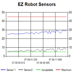
So I have finally gotten to the point of connecting up the waist motor on my B9 to the sabertooth/kangaroo. I wired it through the switching circuit that allows the sabertooth to be switched off from the power supply while remaining connected to the dump battery. All was going well until I connected the battery, The moment I did the motor started up running from the battery. The battery should not feed the sabertooth, its just to dump the regen voltage from the motor. The power supply was not connected at this point. For some reason the Mosfet that switches off the supply to the sabertooth was closing as soon as the battery was connected even though there was no supply to the signal pin. I was getting all sorts of weird voltages in places there should have been no voltage. I spent most of the day on it checking and changing diodes which seemed to be fine some times and not others, changing transistors and mosfets and just generally pulling my hair out..... and quite a bit of swearing.
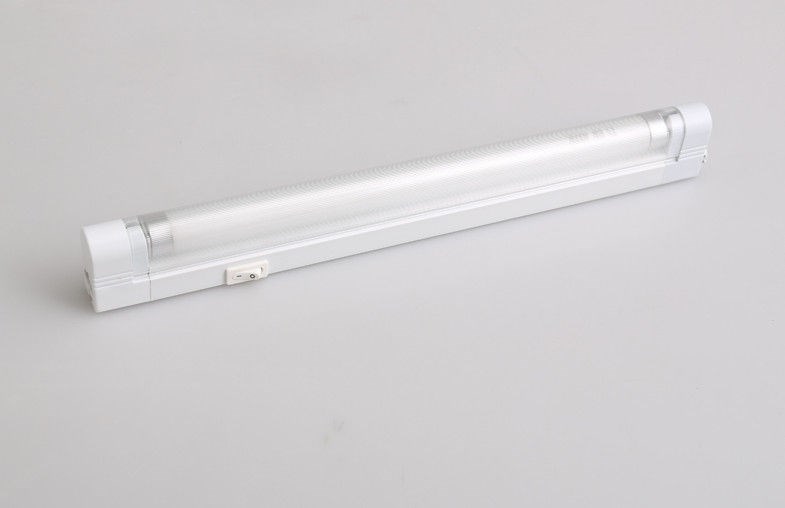
Long story short, the cause of my woes was the light I was using to work with. It was an electronic fluorescent which most of the time, was quite close to everything and inducing a voltage into the wiring and closing the mosfet and transistor. I worked it out when I moved the light near my multimeter leads, which were just sitting on the table at the time, and the voltage reading went up from zero to about 10 volts. Turned the light off and... Eureka! It works.
As a result of this ..... setback, I haven't had time to get the sabertooth/kangaroo tuned as yet like I had planned. I may need some help with that one when I get back to it in a few days
Steve
Good find Steve, that must have been terribly frustrating. Always harder to troubleshoot when the results are not consistent. I usually advise people to change one variable at a time and take notes when tracking down difficult problems, but that wouldn't have helped here since two runs of the same test could have had totally different results.
Alan
Yes very frustrating to say the least. Its quite a simple circuit with only a few components and not too much to go wrong... so I thought. I was getting a different voltage in some places each time I checked. I had diodes appearing to passing 12 volts in one direction as you would expect and anywhere between 3 to 9 volts in the wrong direction. I'd pull them out and then they seemed to be fine when tested by themselves. I just couldn't see how the mosfet was closing. had to keep walking away from it or I was going to smash it.... or burst into tears