
TeddyJenks
Newbie Robosapien V1 Question
Hello everyone,
I'm new to this whole thing, and just had a couple questions before I start soldering. I got my EZ Robot kit today, and have been messing around with the basic tutorials to get a hang of everything. I have a Robosapien V1 that I am trying to hack using the provided video. However, once I popped the sapien open I found that the PCBs were labeled differently than in the video.
I think that I figured out the main board. The board has HMD-01 REV:02 printed on it. The problem with this one is that there is no "IR" pad, but there is one labeled "OUT1" that is in basically the same place. Am I correct in assuming that they are the same?
The second board, the power switch, is also labeled differently. I am trying to power the EZ-B using the foot batteries in the bot. From left to right there are pads "V-IN", "V-OUT", "FREE", "VCC", and "FREE". I am assuming that I would wire to the "V-IN" and "V-OUT", and the IN wire would be positive while the OUT would be negative when connecting to the power adapter. Am I right?
My goal for this guy and his other Robosapien companion that I picked up cheap on ebay is to add a camera like in the video. Plus I am going to try object avoidance, and hopefully eventually somehow find a way to make the two bots interact in some way (hide & seek, follow the leader, etc.)
Any help would be appreciated. I just want to make sure I am doing this right before I ruin something.
Thanks!

So I figured out the IR problem, and it was as I suspected. I've got the Robosapiens up and walking about with a Wii remote.
If anybody could please help with the power switch problem I would appreciate it, because I am not as sure about that part. I'm only asking because I am new to the whole hardware/electronics aspect of robotics.
CHECK MY ROBORAD V1 DESIGN for info ,it uses robosapiens robots
my roborad project
I have a Robosapien V1 also will start thinking with it in a few hours. Can you please upload a pic of your power switch area.
@robotmaker
Thanks, it looks like you have some cool ideas for your Robosapiens. I'm just curious how to wire the power switches to the EZ-B, because my circuit boards look different compared to the tutorial video.
@pjdatechy
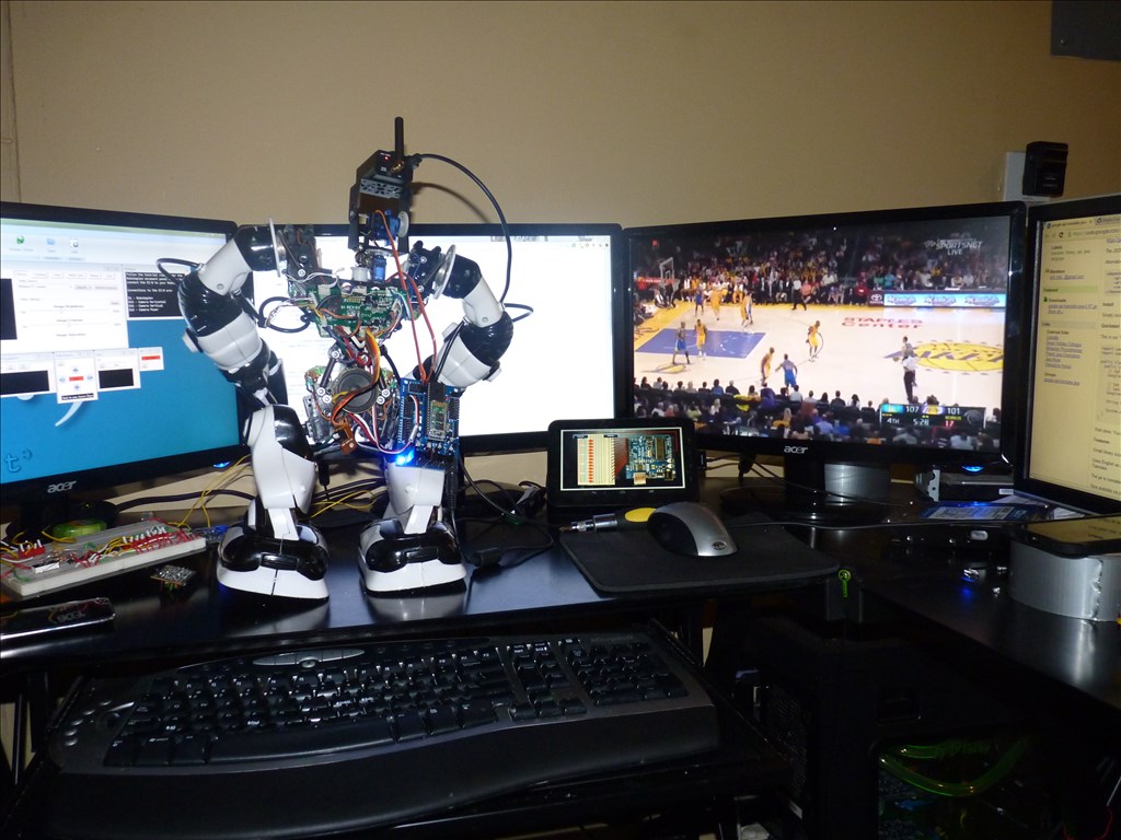
Here are some pictures of the two different Robosapiens and their power switches.
The bottom board is a little dirty, it says "V IN" on the right.
Sorry it took so long to reply, but after 4 hours of it being on the operation table, He is alive and functioning well, still have some minor issues like camera tracking but maybe tomorrow. To answer your questions the Out 1 is the same as ir or input signals. For Power I testested with a multimeter. V-out, positive ( red wire) and free ( any one of the brown wires) negative or ground. lol didnt really care about the head , it got beheaded ( still preserve the interiors components of course).
Cool! Thank you for the help. It looks like it's time for me to operate on my Robosapien this weekend. Are you going to mount the camera where the head used to be? That would be pretty cool!
Some of the components for the IR receiver, along with a tiny circuit for the led's were filter through the neck in the very center. So I mounted it on the side, but the problem I have the camera added a little bit too much weight on one side. It have difficulty walking, or lifting the right leg up properly. Today I will focus on scripting and making the wireless camera work, but I'm thinking on purchasing a rover chassis and mount my robosapien. Also since I am a big car person, minimal weight + power = speed. The Robosapien carry 4x D cell batteries, those suckers are heavy, i'm thinking about replacing them with a 7.2v rechargeable battery I took out of my AC Helicopter. 2x D batteries are spitting out 3v to each side, so a total of 6v. A simple voltage regulator or voltage divider will do the trick, I think.
So PJ, Once again, glad to see you back. I'm EZing my V1 right now following the Video Tutorial and I'm pretty sure I have the main board good. Thanks to some help from some others I have my signal going to the IR Out and my Ground to GR/ I'm pretty confident that it's good but I'm trying to power my ezb via robosapien like in the video. I have the power switch in the first picture. You said positive to Vcc (Which I have already) and ground to either of the FR? I'm guessing FR is free? Can you confirm this for me?
Thanks